Nissan Sentra Service Manual: Wiring diagram
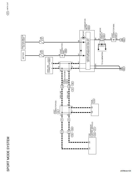
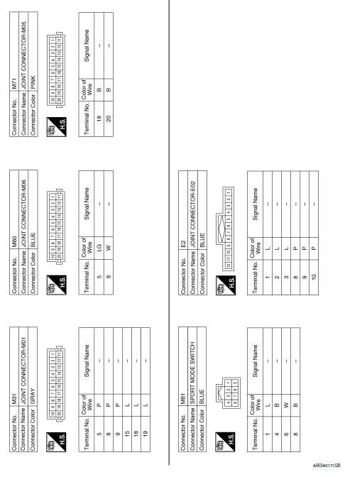
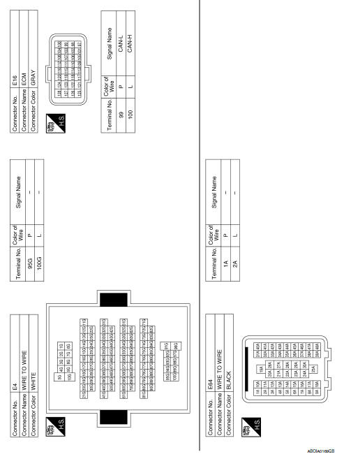
Sport mode system
Wiring diagram
 Ecu diagnosis information
Ecm
List of ecu reference
Reference list
...
 Basic inspection
Diagnosis and repair work flow
Work flow
Overall sequence
Detailed flow
1.Get information for symptom
Get the detailed information from the customer about the symptom (the
condition and the ...
Other materials:
Diagnosis system (ipdm e/r) (without intelligent key system)
Diagnosis Description
AUTO ACTIVE TEST
Description
In auto active test, the IPDM E/R sends a drive signal to the following
systems to check their operation.
Front wiper (LO, HI)
Parking lamp
License plate lamp
Tail lamp
Front fog lamp (if equipped)
Headlamp (LO, HI)
A/C compres ...
Main power supply and ground circuit
Diagnosis Procedure
1.CHECK TCM POWER CIRCUIT (PART 1)
Turn ignition switch OFF.
Disconnect TCM connector.
Check voltage between TCM harness connector terminals and ground.
Is the inspection result normal?
YES >> GO TO 2.
NO >> GO TO 4.
2.CHECK TCM POWER CIRCUIT (PAR ...
P0111 IAT Sensor
DTC Logic
DTC DETECTION LOGIC
DTC No.
CONSULT screen terms
(Trouble diagnosis content)
DTC detecting condition
Possible cause
P0111
IAT SENSOR 1 B1
(Intake air temperature sensor 1
circuit range/performance bank 1)
The comparison result of signals transmitte ...
