Nissan Sentra Service Manual: Main power supply and ground circuit
Diagnosis Procedure
1.CHECK TCM POWER CIRCUIT (PART 1)
- Turn ignition switch OFF.
- Disconnect TCM connector.
- Check voltage between TCM harness connector terminals and ground.
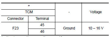
Is the inspection result normal? YES >> GO TO 2.
NO >> GO TO 4.
2.CHECK TCM POWER CIRCUIT (PART 2)
Check voltage between TCM harness connector terminals and ground.
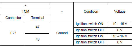
Is the inspection result normal? YES >> GO TO 3.
NO >> GO TO 5.
3.CHECK TCM GROUND CIRCUIT
Check continuity between TCM harness connector terminals and ground.
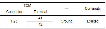 Is the inspection
result normal?
YES >> Check intermittent incident. Refer to GI-39, "Intermittent Incident".
NO >> Repair or replace malfunctioning parts.
4.DETECT MALFUNCTION ITEMS (PART 1)
Check the following items:
- Open or short circuit of harness between battery positive terminal and
TCM connector terminals 45 and 46.
Refer to PG-8, "Wiring Diagram — Battery Power Supply —".
- 10A fuse (No.33, fuse and fusible link block). Refer to PG-48, "Terminal Arrangement".
- 10A fuse (No.36, fuse and fusible link block). Refer to PG-48, "Terminal Arrangement".
Is the inspection result normal? YES >> Check intermittent incident. Refer to GI-39, "Intermittent Incident".
NO >> Repair or replace malfunctioning parts.
5.DETECT MALFUNCTIONING ITEMS (PART 2)
Check the following items:
- Harness open circuit or short circuit between ignition switch and IPDM E/R. Refer to PG-20, "Wiring Diagram — Ignition Power Supply —".
- Harness open circuit or short circuit between IPDM E/R and TCM.
- 10A fuse (No.45, IPDM E/R). Refer to PG-48, "Terminal Arrangement".
- IPDM E/R
Is the check result normal? YES >> Check intermittent incident. Refer to GI-39, "Intermittent Incident".
NO >> Repair or replace malfunctioning parts.
 P285A Clutch B Pressure
DTC Logic
DTC DETECTION LOGIC
DTC
CONSULT screen terms
(Trouble diagnosis content)
DTC detection condition
Possible causes
P285A
CLUTCH B PRESSURE
(Clutch B Pressur ...
 Overdrive control switch
Component Function Check
1.CHECK SPORT INDICATOR LAMP FUNCTION
Check OD OFF indicator lamp turns ON for approx. 2 seconds when ignition
switch turns ON.
Is the inspection result normal?
YES &g ...
Other materials:
On board diagnostic (OBD) system
Diagnosis Description
This system is an on board diagnostic system that records exhaust
emission-related diagnostic information
and detects a sensors/actuator-related malfunction. A malfunction is indicated
by the malfunction indicator
lamp (MIL) and stored in ECU memory as a DTC. The diagnos ...
CSC(concentric slave cylinder)
Exploded View
Transaxle assembly
CSC (Concentric Slave Cylinder)
Removal and Installation
CAUTION:
Do not reuse CSC (Concentric Slave Cylinder). The CSC slides back
to the original position every
time the transaxle assembly is removed. This action may allow dust or
contamin ...
Tire Pressure Monitoring System (TPMS)
This vehicle is equipped with the Tire Pressure
Monitoring System (TPMS). It monitors tire pressure
of all tires except the spare. When the low
tire pressure warning light is lit, and the CHECK
TIRE PRES warning message is displayed in the
odometer, one or more of your tires is significantly
u ...
