Nissan Sentra Service Manual: Rear disc brake
BRAKE PAD
BRAKE PAD : Exploded View
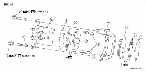
- Upper sliding pin bolt
- Lower sliding pin bolt
- Bushing
- Cylinder body
- Inner shim cover
- Inner shim
- Inner pad (with pad wear sensor)
- Pad retainer
- Torque member
- Outer pad
- Outer shim
- Outer shim cover
- Apply rubber grease
- Molykote AS880N
BRAKE PAD : Removal and Installation
REMOVAL
WARNING:
Clean dust on brake caliper and brake pad with a vacuum dust collector to minimize the hazards of airborne particles or other material.
CAUTION:
- Do not depress the brake pedal while removing the brake pads because the pistons may pop out.
- It is not necessary to remove bolts on torque member and brake hose except for disassembly or replacement of brake caliper. For brake pad removal, hang brake caliper with a wire so as not to stretch brake hose.
- If brake fluid or grease adheres to the brake caliper or disc rotor, quickly wipe it off.
- Remove rear wheels and tires using power tool. Refer to WT-47, "Removal and Installation".
- Remove sliding pin bolts.
- Remove the brake caliper from the torque member. Leaving brake hose attached, reposition the brake caliper aside with wire.
- Remove the brake pads, shims, shim covers and pad retainers from the torque member.
CAUTION:
- Do not deform the pad retainer (2) when removing the pad retainer from the torque member (1).
- Do not damage the piston boot.
- Do not drop the brake pads, shims, and the shim covers.
- Remember each position of the removed brake pads
INSTALLATION
- Install the pad retainers (1) to the torque member (2) if the pad retainers have been removed.
CAUTION:
- Securely assemble the pad retainers so that it will not be lifted up from the torque member.
- Do not deform the pad retainers.
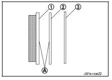
- Apply Molykote AS880N or equivalent to the mating faces (A) between the brake pads (1) and the shims (2), and install the shims and shim covers (3) to the brake pad.
CAUTION:
Always replace the shim and shim cover when replacing the brake pad.
- Install the brake pads to the torque member.
- Using a suitable tool, press the piston into the brake caliper.
CAUTION:
Do not damage the piston boot.
- Install brake caliper to torque member.
- Install the sliding pin bolts and tighten them to the specified torque.
- Depress the brake pedal several times to verify that drag does not exist.
- Install rear wheels and tires. Refer to WT-47, "Removal and Installation".
Brake caliper assembly
BRAKE CALIPER ASSEMBLY : Exploded View
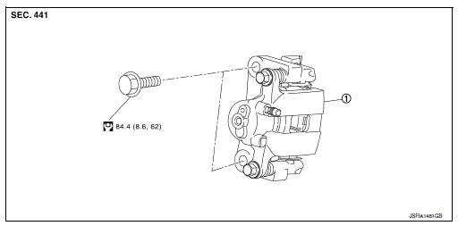
- Brake caliper assembly
BRAKE CALIPER ASSEMBLY : Removal and Installation
REMOVAL
WARNING:
Clean dust on brake caliper and brake pad with a vacuum dust collector to minimize the hazard of airborne particles or other materials.
CAUTION:
- Do not depress the brake pedal.
- Do not spill or splash brake fluid on painted surfaces. Brake fluid may damage paint. If brake fluid is splashed on painted areas, wash it away with water immediately.
- Do not bend, twist or pull the brake hoses and piping.
- Do not reuse drained brake fluid.
NOTE:
When removing components such as hoses, tubes/lines, etc., cap or plug openings to prevent fluid from spilling.
- Remove rear wheels and tires using power tool. Refer to WT-47, "Removal and Installation".
- Secure the disc rotor using wheel nuts.
- Remove union bolt, copper sealing washers, and disconnect brake hose from brake caliper. Discard the copper sealing washers.
CAUTION:
Do not reuse copper sealing washers.
- Remove sliding pin bolts, and remove brake caliper assembly.
INSTALLATION
- Position the brake caliper to torque member and install the sliding pin bolts. Tighten to specification.
- Position the brake caliper and torque member to the vehicle as an assembly. Install the torque member bolts.
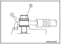
- Assemble the union bolt (A) and the copper sealing washers (1)
to the brake hose and install it as an assembly to the brake caliper.
Align the brake hose L-pin by aligning it with the brake caliper hole, and tighten the union bolt (A) to the specified torque.
CAUTION:
Do not reuse copper sealing washers.
- Refill with new brake fluid and perform the air bleeding. Refer to BR-17, "Bleeding Brake System".
CAUTION:
- Do not reuse drained brake fluid.
- Do not spill or splash brake fluid on the disc rotor.
- Check the rear disc brakes for drag. If drag exists, refer to BR- 14, "BRAKE PAD : Inspection".
- Install the rear wheels and tires. Refer to WT-47, "Removal and Installation".
 Rear drum brake
BRAKE CALIPER ASSEMBLY : Exploded View
Shoe hold pin
Back plate
Plug
Brake shoe
Spring
Upper spring
Adjuster
Return spring
Brake drum
Boot
Piston
Piston cup
Spring
W ...

Other materials:
Brake pedal
Inspection
BRAKE PEDAL HEIGHT
Check the brake pedal height (H1) between the dash lower panel (1)
and the brake pedal upper surface.
Brake pedal height (H1) : Refer to BR-54, "Brake Pedal".
CAUTION:
Check the brake pedal height with the floor trim removed.
STOP LAMP SWITCH AND BR ...
Glass lid
Exploded view
Glass lid
Roof panel
Front
Removal and installation
Removal
Caution:
After installing glass lid, check gap/height adjustments and
operation to make sure there is no malfunction.
Handle glass lid with care to prevent damage.
Open sunshade (1), then close ...
Unit removal and installation
TRANSMISSION ASSEMBLY
Exploded View
Transaxle assembly
O-ring
CVT fluid charging pipe
CVT fluid charging pipe cap
Tightening must be done following the installation procedure. Refer to
TM-283, "Removal and Installation".
: Always replace after every
disassemb ...
