Nissan Sentra Service Manual: Brake pedal
Inspection
BRAKE PEDAL HEIGHT
Check the brake pedal height (H1) between the dash lower panel (1) and the brake pedal upper surface.
Brake pedal height (H1) : Refer to BR-54, "Brake Pedal".
CAUTION:
Check the brake pedal height with the floor trim removed.
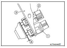
STOP LAMP SWITCH AND BRAKE PEDAL POSITION SWITCH
Check the clearance (A) between the switch assembly bracket (3), the stop lamp switch (2) and the brake pedal position switch (if equipped) (1).
Clearance (A) : Refer to BR-54, "Brake Pedal".
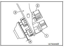
STOP LAMP SWITCH AND BRAKE PEDAL POSITION SWITCH
Check the clearance (A) between the switch assembly bracket (3), the stop lamp switch (2) and the brake pedal position switch (if equipped) (1).
Clearance (A) : Refer to BR-54, "Brake Pedal".
CAUTION:
The stop lamp must turn off when the brake pedal is released.
NOTE:
Pull the brake pedal pad to check that both the stop lamp switch (2) and brake pedal position switch (1) contact ends to brake pedal bracket (3) clearance (A) are within specification.
BRAKE PEDAL PLAY
Check that brake pedal play does not exist.
DEPRESSED BRAKE PEDAL HEIGHT
Check the brake pedal height (H2) between the dash lower panel (1) and the brake pedal upper surface when depressing the brake pedal at 490 N (50 kg, 110 lb) while turning engine ON.
Depressed brake pedal height (H2) : Refer to BR-54, "Brake Pedal".
CAUTION:
Check the depressed brake pedal height with the floor trim removed.
 Basic inspection
...
 Brake fluid
Inspection
BRAKE FLUID LEVEL
Make sure that the brake fluid level in the reservoir tank is between
the MAX and MIN lines.
Visually check around the reservoir tank for brake fluid leakage.
I ...
Other materials:
Diagnosis system (ipdm e/r) (without intelligent key system)
Diagnosis Description
AUTO ACTIVE TEST
Description
In auto active test, the IPDM E/R sends a drive signal to the following
systems to check their operation.
Front wiper (LO, HI)
Parking lamp
License plate lamp
Tail lamp
Front fog lamp (if equipped)
Headlamp (LO, HI)
A/C compres ...
DTC/Circuit diagnosis
POSITION SWITCH
BACK-UP LAMP SWITCH
BACK-UP LAMP SWITCH : Component Inspection
1.CHECK BACK-UP LAMP SWITCH
Disconnect position switch harness connector. Refer to TM-21, "Removal
and Installation".
Check continuity between position switch terminals.
Is the inspection ...
Wiper and washer system symptoms
Symptom table
Caution:
Perform the self-diagnosis with consult before performing the diagnosis
by symptom. Perform the
diagnosis by dtc if dtc is detected.
...
