Nissan Sentra Service Manual: Exhaust valve timing control
EXHAUST VALVE TIMING CONTROL : System Description
SYSTEM DIAGRAM
INPUT/OUTPUT SIGNAL CHART
| Sensor | Input signal to ECM | ECM function | Actuator | |
| Crankshaft position sensor (POS) | Engine speed and piston position | Exhaust valve timing control | Exhaust valve timing control solenoid valve | |
| Camshaft position sensor (PHASE) | ||||
| Engine oil temperature sensor | Engine oil temperature | |||
| Exhaust valve timing control position sensor | Exhaust valve timing signal | |||
| Combination meter | CAN communication | Vehicle speed signal | ||
SYSTEM DESCRIPTION
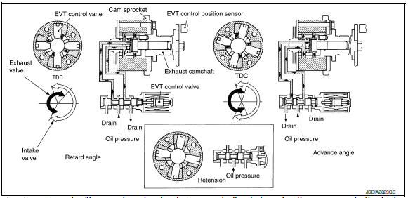
This engine is equipped with an exhaust valve timing controller (integral with cam sprocket) which continuously adjusts the phase of intake valve according to driving conditions, improves both low/mid range engine torque and high-speed range engine output, and brings about low emission and low fuel consumption.
The exhaust valve timing control system continuously controls cam phases in constant exhaust valve operating angle conditions and adjusts an operating oil pressure to the exhaust valve timing controller via the control solenoid valve.
ECM receives exhaust valve timing control position signal, crankshaft position signal, engine speed signal, engine oil temperature signal, and engine coolant temperature signal. And the ECM outputs ON/OFF pulse duty signals to the exhaust valve timing control solenoid valve depending on driving status.
Exhaust Valve Timing Controller Operation List
| Exhaust valve timing solenoid valve condition | Exhaust valve timing controller operation |
| Engine OFF | When starting the engine, the controller vane and sprocket are fixed in full retard position by the reaction force of return spring, improving the starting performance of the engine. |
| Active (Retard angle) | When the energization rate to the control solenoid valve is
increased, the oil pressure from the oil
pump is conveyed to the retard angle chamber of the controller. And
advance angle chamber oil is
drained. Accordingly, the controller vane rotates leftward and the phase
of camshaft becomes retard
angle.
This condition brings about the greater overlap with the exhaust valve, enabling the exhaust gas cleaning by the internal EGR effect and the fuel consumption improvement by the reduction in pumping loss. |
| Neutral (Maintained) | When it is the target valve timing, the energization rate to the control solenoid valve is adjusted to the intermediate state. The solenoid valve is positioned at the neutral position and the oil path is interrupted to maintain the cam shaft phase. |
| Return (Advance angle) | When the energization rate to the control solenoid valve is
decreased, the oil pressure from the oil
pump is conveyed to the advance angle chamber of the controller. And
retard angle chamber oil is
drained.
Accordingly, the controller vane rotates rightward and the phase of camshaft becomes advance angle. |
EXHAUST VALVE TIMING CONTROL FEEDBACK CONTROL
Cam Position Detection
The exhaust valve control position sensor mounted at the rear of the cylinder head detects a cam position, by using the groove on the plate located at the rear of the intake camshaft.
Feedback Control
The exhaust valve control position sensor feeds back an actual cam position signal to ECM. Based on the signal, ECM controls the exhaust valve timing control solenoid valve to satisfy the optimum target valve opening/ closing timing according to a driving condition.
 Intake valve timing control
INTAKE VALVE TIMING CONTROL : System Description
SYSTEM DIAGRAM
INPUT/OUTPUT SIGNAL CHART
Sensor
Input signal to ECM
ECM function
Actuator
Crankshaft position sensor (P ...
 Intake manifold runner control
INTAKE MANIFOLD RUNNER CONTROL : System
Description
SYSTEM DIAGRAM
SYSTEM DESCRIPTION
Intake manifold runner control valve has a valve portion in the intake
passage of each cylinder.
Whil ...
Other materials:
Can communication circuit
Diagnosis procedure
1.Connector inspection
Turn the ignition switch OFF.
Disconnect the battery cable from the negative terminal.
Disconnect all the unit connectors on can communication system.
Check terminals and connectors for damage, bend and loose connection.
Is the inspection resu ...
Clutch fluid
Inspection
FLUID LEAKAGE
Check clutch line for cracks, deterioration or other damage. Replace any
damaged parts.
Check for fluid leakage by fully depressing clutch pedal while engine is
running.
CAUTION:
If leakage occurs around connections, reinstall the lines or replace
damaged ...
Fuel gauge
NOTE:
The ignition switch must be placed in the
ON position for the gauge to give a reading.
The gauge indicates the approximate fuel level
in the tank.
The gauge may move slightly during braking,
turning, acceleration, or going up or down hills.
The low fuel warning light comes on when ...
