Nissan Sentra Service Manual: Intake manifold runner control
INTAKE MANIFOLD RUNNER CONTROL : System Description
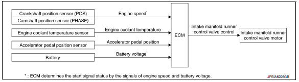
SYSTEM DIAGRAM
SYSTEM DESCRIPTION
Intake manifold runner control valve has a valve portion in the intake passage of each cylinder.
While idling and during low engine coolant temperature, the intake manifold runner control valve closes. Thus the velocity of the air in the intake passage increases, promoting the vaporization of the fuel and producing a intake manifold runner in the combustion chamber.
Because of this operation, this system tends to increase the burning speed of the gas mixture, improve exhaust emission, and increase the stability in running conditions.
Also, except when idling and during low engine coolant temperature, this system opens the intake manifold runner control valve.
In this condition, this system tends to increase power by improving intake efficiency via reduction of intake flow resistance.
The intake manifold runner control valve is operated by the ECM.
 Exhaust valve timing control
EXHAUST VALVE TIMING CONTROL : System
Description
SYSTEM DIAGRAM
INPUT/OUTPUT SIGNAL CHART
Sensor
Input signal to ECM
ECM function
Actuator
Crankshaft position sensor ...
 Intake manifold tuning system
INTAKE MANIFOLD TUNING SYSTEM : System
Description
SYSTEM DIAGRAM
SYSTEM DESCRIPTION
This system switches the length of intake air path according to the
low-to-medium speed range or high spe ...
Other materials:
Rear window defogger power supply and ground circuit
Description
Heats the heating wire with the power supply from the rear window defogger
relay to prevent the rear window
from fogging up.
Component function check
1. Check rear window defogger
Check that the heating wire of rear window defogger is heated when turning
the rear window defogge ...
Tightening Torque Table (New Standard Included)
CAUTION:
The special parts are excluded.
The bolts/nuts in these tables have a strength (discrimination)
number/symbol assigned to the head
or the like. As to the relation between the strength grade in these tables
and the strength (discrimination)
number/symbol, refer to “DISCR ...
Diagnosis system (bcm) (without intelligent key system)
Common item
COMMON ITEM : CONSULT Function (BCM - COMMON ITEM)
APPLICATION ITEM
CONSULT performs the following functions via CAN communication with BCM.
SYSTEM APPLICATION
BCM can perform the following functions.
Wiper
Wiper : consult function (bcm - wiper)
DATA MONITOR
ACTIVE TES ...
