Nissan Sentra Service Manual: Overdrive control switch
Component Function Check
1.CHECK SPORT INDICATOR LAMP FUNCTION
Check OD OFF indicator lamp turns ON for approx. 2 seconds when ignition switch turns ON.
Is the inspection result normal? YES >> GO TO 2.
NO >> Go to TM-239, "Diagnosis Procedure".
2.CHECK SPORT MODE SWITCH FUNCTION
- Shift the selector lever to “D” position.
- Check that OD OFF indicator lamp turns ON/OFF when overdrive control switch is operated.
Is the inspection result normal? YES >> INSPECTION END
NO >> Go to TM-236, "Diagnosis Procedure".
Diagnosis Procedure
1.CHECK OVERDRIVE CONTROL SWITCH CIRCUIT
- Turn ignition switch OFF
- Disconnect CVT shift selector connector.
- Turn ignition switch ON.
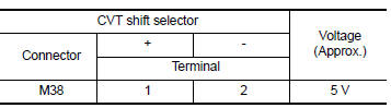
- Check voltage between CVT shift selector harness connector terminals.
 Is the inspection
result normal?
YES >> GO TO 2.
NO >> GO TO 4.
2.CHECK CVT SHIFT SELECTOR ASSEMBLY
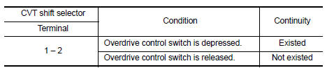
Check continuity between CVT shift selector connector terminals.
 Is the inspection
result normal?
YES >> Check intermittent incident. Refer to GI-39, "Intermittent Incident".
NO >> GO TO 3.
3.CHECK OVERDRIVE CONTROL SWITCH
Check overdrive control switch. Refer to TM-237, "Component Inspection (Overdrive Control Switch)".
Is the inspection result normal? YES >> Replace CVT shift selector assembly. Refer to TM-253, "Removal and Installation".
NO >> Repair or replace malfunctioning parts.
4.CHECK GROUND CIRCUIT
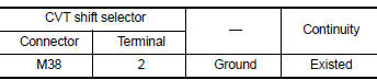
Check continuity between CVT shift selector harness connector terminal and ground.
 Is the inspection
result normal?
YES >> GO TO 5.
NO >> Repair or replace malfunctioning parts.
5.CHECK CIRCUIT BETWEEN COMBINATION METER AND CVT SHIFT SELECTOR (PART 1)
- Turn ignition switch OFF
- Disconnect combination meter connector.
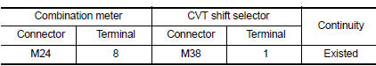
- Check continuity between combination meter harness connector terminal and CVT shift selector harness connector terminal.
 Is the inspection
result normal?
YES >> GO TO 6.
NO >> Repair or replace malfunctioning parts.
6.CHECK CIRCUIT BETWEEN COMBINATION METER AND CVT SHIFT SELECTOR (PART 2)
Check continuity between combination meter harness connector terminal and ground.
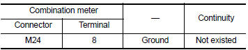 Is the inspection
result normal?
YES >> GO TO 7.
NO >> Repair or replace malfunctioning parts.
7.CHECK COMBINATION METER INPUT SIGNAL
- Connect all of disconnected connectors.
- Turn ignition switch ON.
- Select “Data Monitor” in “METER/M&A”.
- Select “O/D OFF SW”.
- Check that “O/D OFF SW” turns ON/OFF when overdrive control switch is operated. Refer to MWI-20, "Reference Value".
Is the inspection result normal? YES >> Check intermittent incident. Refer to GI-39, "Intermittent Incident".
NO >> Replace combination meter. Refer to MWI-77, "Removal and Installation".
Component Inspection (Overdrive Control Switch)
1.Check overdrive control switch
Check continuity between wires of selector lever knob 1.
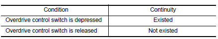 Is the inspection
result normal?
YES >> INSPECTION END
NO >> Replace selector lever knob. Refer to TM-253, "Removal and Installation".
 Main power supply and ground circuit
Diagnosis Procedure
1.CHECK TCM POWER CIRCUIT (PART 1)
Turn ignition switch OFF.
Disconnect TCM connector.
Check voltage between TCM harness connector terminals and ground.
Is the insp ...
 Od off indicator lamp
Component Function Check
1.CHECK OD OFF INDICATOR LAMP FUNCTION
Check OD OFF indicator lamp turns ON for approx. 2 seconds when ignition
switch turns ON.
Is the inspection result normal?
YES ...
Other materials:
Wiring diagram
Display audio without bose
Wiring diagram
...
Periodic maintenance
Introduction of periodic maintenance
The following tables show the normal maintenance schedule. Depending upon
weather and atmospheric conditions,
varying road surfaces, individual driving habits and vehicle usage, additional
or more frequent maintenance
may be required.
Periodic maintenan ...
Front disc brake
BRAKE PAD
BRAKE PAD : Inspection
PAD WEAR
Check brake pad thickness from an inspection hole on caliper body.
Check using a scale if necessary
Wear limit thickness : Refer to BR-55, "Front Disc
Brake".
DISC ROTOR
DISC ROTOR : Inspection
APPEARANCE
Check surface of disc rotor ...
