Nissan Sentra Service Manual: P0111 IAT Sensor
DTC Logic
DTC DETECTION LOGIC
| DTC No. | CONSULT screen terms (Trouble diagnosis content) | DTC detecting condition | Possible cause |
| P0111 | IAT SENSOR 1 B1 (Intake air temperature sensor 1 circuit range/performance bank 1) | The comparison result of signals transmitted to ECM from each temperature sensor (IAT sensor, ECT sensor, FTT sensor, and EOT sensor) shows that the voltage signal of the IAT sensor is higher/lower than that of other temperature sensors when the engine is started with its cold state. |
|
DTC CONFIRMATION PROCEDURE
1.INSPECTION START
Is it necessary to erase permanent DTC? YES >> GO TO 3.
NO >> GO TO 2.
2.PERFORM COMPONENT FUNCTION CHECK
Perform component function check. Refer to EC-193, "Component Function Check".
NOTE:
Use the component function check to check the overall function of the IAT sensor circuit. During this check, a 1st trip DTC might not be confirmed.
Is the inspection result normal? YES >> INSPECTION END
NO >> Proceed to EC-193, "Diagnosis Procedure".
3.PRECONDITIONING
If DTC CONFIRMATION PROCEDURE has been previously conducted, always perform the following procedure before conducting the next test.
- Turn ignition switch OFF and wait at least 10 seconds.
- Turn ignition switch ON.
- Turn ignition switch OFF and wait at least 10 seconds.
TESTING CONDITION:
- Before performing the following procedure, do not add fuel.
- Before performing the following procedure, check that fuel level is between 1/4 and 4/4.
- Before performing the following procedure, confirm that battery voltage is 11 V or more at idle.
>> GO TO 4.
4.PERFORM DTC CONFIRMATION PROCEDURE
- Move the vehicle to a cool place.
NOTE:
Cool the vehicle in an environment of ambient air temperature between −10В°C (14В°F) and 35В°C (95В°F).
- Turn ignition switch OFF and leave the vehicle for 12 hours.
CAUTION:
Never turn ignition switch ON during this procedure.
NOTE:
The vehicle must be cooled with the food open.
- Start engine and let it idle for 5 minutes or more.
CAUTION:
Never turn ignition switch OFF during idling.
- Check 1st trip DTC.
Is 1st trip DTC detected? YES >> Proceed to EC-193, "Diagnosis Procedure".
NO >> INSPECTION END
Component Function Check
1.CHECK INTAKE AIR TEMPERATURE (IAT) SENSOR
- Turn ignition switch OFF.
- Disconnect mass air flow sensor harness connector and reconnect it again.
- Turn ignition switch ON.
- Select “DATA MONITOR” mode with CONSULT
- Check that “INT/A TEMP SEN” indicates as per following condition.
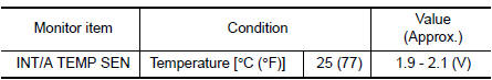
Is the inspection result normal? YES >> Check intermittent incident. Refer to GI-39, "Intermittent Incident".
NO >> Proceed to EC-193, "Diagnosis Procedure".
Diagnosis Procedure
1.CHECK INTAKE AIR TEMPERATURE (IAT) SENSOR
Check intake air temperature sensor. Refer toEC-193, "Component Inspection".
Is the inspection result normal? YES >> Check intermittent incident. Refer to GI-39, "Intermittent Incident".
NO >> Replace mass air flow sensor (with intake air temperature sensor). Refer to EM-25, "Exploded View".
Component Inspection
1.CHECK INTAKE AIR TEMPERATURE SENSOR
- Turn ignition switch OFF.
- Disconnect mass air flow sensor harness connector and reconnect it again.
- Turn ignition switch ON.
- Select “DATA MONITOR” mode with CONSULT.
- Check that the indicated value of “INT/A TEMP SEN” is almost the same as intake air temperature.
Is the inspection result normal? YES >> INSPECTION END
NO >> Replace mass air flow sensor (with intake air temperature sensor). Refer to EM-25, "Exploded View".
 P0101, P0102, P0103 MAF Sensor
DTC Logic
DTC DETECTION LOGIC
DTC No.
CONSULT screen terms
(Trouble diagnosis content)
DTC detecting condition
Possible cause
P0101
MAF SEN/CIRCUIT-B1
(Mass or volu ...
 P0112, P0113 IAT Sensor
DTC Logic
DTC DETECTION LOGIC
DTC No.
CONSULT screen terms
(Trouble diagnosis content)
DTC detecting condition
Possible cause
P0112
IAT SEN/CIRCUIT- B1
(Intake air ...
Other materials:
OIL
Description
MAINTENANCE OF OIL LEVEL
The compressor oil is circulating in the system together with the
refrigerant. It is necessary to fill compressor
with oil when replacing A/C system parts or when a large amount of refrigerant
leakage is detected. It is important
to always maintain oil l ...
Operating tips
When the engine coolant temperature and
outside air temperature are low, the air flow
from the foot outlets may not operate for a
maximum of 150 seconds. However, this is
not a malfunction. After the coolant temperature
warms up, air flow from the foot outlets
will operate normally.
...
Rear bumper
Exploded view
Rear bumper side bracket (LH)
Rear bumper reinforcement
Rear bumper energy absorber
Rear bumper fascia reflector (LH)
Rear bumper fascia reflector (RH)
Rear bumper fascia
Rear bumper side bracket (RH)
Pawl
Removal and installation
CAUTION:
Bumper fascia is ma ...
