Nissan Sentra Service Manual: OIL
Description
MAINTENANCE OF OIL LEVEL
The compressor oil is circulating in the system together with the refrigerant. It is necessary to fill compressor with oil when replacing A/C system parts or when a large amount of refrigerant leakage is detected. It is important to always maintain oil level within the specified level, otherwise the following conditions may occur:
- Insufficient oil amount: Stuck compressor
- Excessive oil amount: Insufficient cooling (caused by insufficient heat exchange)
Oil Type : A/C System Oil Type DH-PS
Inspection
If a compressor is malfunctioning (internal noise, insufficient cooling), check the compressor oil.
1.COMPRESSOR OIL JUDGMENT
- Remove the compressor. Refer to HA-31, "COMPRESSOR : Removal and Installation".
- Sample compressor oil and judge below according to the figure.
Judgement result 1>>Replace compressor only.
Judgement result 2>>Replace compressor and liquid tank.
Perform oil return operation
CAUTION:
If a large amount of refrigerant or oil leakage is detected, do not perform oil return operation.
- Start the engine and set to the following conditions:
- Engine speed: Idling to 1,200 rpm
- A/C switch: ON
- Fan (blower) speed: Maximum speed set
- Intake door position: Recirculation
- Temperature setting: Full cold
- Perform oil return operation for approximately 10 minutes.
- Stop the engine.
- Oil return operation is complete
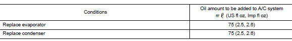
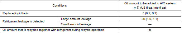
Oil adjusting procedure for components replacement except compressor
Fill with oil for the amount that is calculated according to the following conditions.
Example: Oil amount to be added when replacing evaporator and liquid tank [m (US fl oz, Imp fl oz)] = 45 (1.5, 1.6) + 15 (0.5, 0.5) + α
Oil adjusting procedure for compressor replacement
- New compressor
- Old compressor
- Recovery/recycling equipment
- Measuring cup X
- Measuring cup Y
- New oil
- Drain oil from the new compressor into clean container
- Record amount of oil recovered
- Add an additional 5 m (0.2 US fl oz, 0.2 Imp fl oz) of new oil when replacing liquid tank
- Install new oil equal to recorded amounts in measuring cups X plus Y
- Before connecting recovery/recycling equipment to vehicle, check
recovery/recycling equipment gauges.
No refrigerant pressure should be displayed. If NG, recover refrigerant from equipment lines.
- Connect recovery/recycling equipment to vehicle. Confirm refrigerant purity in supply tank using recovery/ recycling equipment and refrigerant identifier. If NG, refer to HA-4, "Precautions For Refrigerant System Service".
- Confirm refrigerant purity in vehicle A/C system using
recovery/recycling equipment and refrigerant identifier.
If NG, refer to HA-4, "Precautions For Refrigerant System Service".
- Discharge refrigerant into the refrigerant recovery/recycling equipment. Measure oil discharged into the recovery/recycling equipment.
- Drain the oil from the “old” (removed) compressor into a graduated container and recover the amount of oil drained.
- Drain the oil from the “new” compressor into a separate, clean container.
- Measure an amount of new oil installed equal to amount drained from “old” compressor. Add this oil to “new” compressor through the suction port opening.
- Measure an amount of new oil equal to the amount recovered during discharging. Add this oil to “new” compressor through the suction port opening.
- If the liquid tank also needs to be replaced, add an additional 5 m (0.2 US fl oz, 0.2 Imp fl oz) of oil at this time.
CAUTION:
Do not add the 5 m (0.2 US fl oz, 0.2 Imp fl oz) of oil if only replacing the compressor and not the liquid tank.
 Refrigerant
Description
CONNECTION OF SERVICE TOOLS AND EQUIPMENT
Shut-off valve
A/C service valve
Recovery/recycling/recharging
equipment
Refrigerant container (HFC-134a)
Weight scale (J-3965 ...
 Performance test
Inspection
INSPECTION PROCEDURE
Connect recovery/recycling/recharging equipment (for HFC-134a) or
manifold gauge.
Start the engine, and set to the following condition.
Test condition
...
Other materials:
P2004 Intake manifold runner control valve
DTC Logic
DTC DETECTION LOGIC
DTC No.
CONSULT screen terms
(Trouble diagnosis content)
DTC detecting condition
Possible cause
P2004
TUMBLE CONT/V
(Intake manifold runner control
stuck open bank 1)
The target angle of intake manifold runner
control valve c ...
Variable voltage control system
CAUTION
Do not ground accessories directly to
the battery terminal. Doing so will bypass
the variable voltage control system
and the vehicle battery may not
charge completely.
Use electrical accessories with the engine
running to avoid discharging the
vehicle battery.
Your v ...
Larger children
Children should remain in a forward-facing child
restraint with a harness until they reach the maximum
height or weight limit allowed by the child
restraint manufacturer.
Once a child outgrows the height or weight limit
of the harness-equipped forward-facing child restraint,
NISSAN recommends ...
