Nissan Sentra Service Manual: Basic inspection
Diagnosis and repair work flow
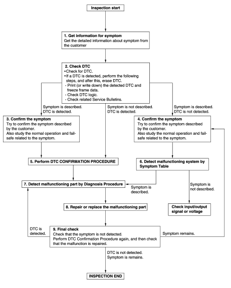
Work flow
Overall sequence

Detailed flow
1.Get information for symptom
Get the detailed information from the customer about the symptom (the condition and the environment when the incident/malfunction occurred) using the “diagnostic work sheet”. (Refer to ec-129, "diagnostic work sheet".) >> Go to 2.
2.Check dtc in ecm
- Check dtc in ecm.
- If a dtc is detected, perform the following steps, and after this, erase dtc.
- Print (or write down) the detected DTC and freeze frame data.
- Check DTC logic.
- Study the relationship between the cause detected by dtc and the symptom described by the customer.
- Check related Service Bulletins
Are any symptoms described and any DTCs detected? Symptom is described, DTC is detected>>GO TO 3.
Symptom is described, DTC is not detected>>GO TO 4.
Symptom is not described, DTC is detected>>GO TO 5.
3.Confirm the symptom
Try to confirm the symptom described by the customer.
Also study the normal operation and fail-safe related to the symptom. Refer to ec-473, "symptom table" and ec-90, "fail safe".
Diagnosis work sheet is useful to verify the incident.
Verify relation between the symptom and the condition when the symptom is detected.
>> Go to 5.
4.Confirm the symptom
Try to confirm the symptom described by the customer.
Verify relation between the symptom and the condition when the symptom is detected.
>> Go to 6.
5.Perform dtc confirmation procedure
Perform DTC CONFIRMATION PROCEDURE for the displayed DTC, and then check that DTC is detected again.
If two or more DTCs are detected, refer to EC-93, "DTC Inspection Priority Chart" and determine trouble diagnosis order.
Note:
- Freeze frame data is useful if the dtc is not detected.
- Perform component function check if dtc confirmation procedure is not
included on service
manual. This simplified check procedure is an effective alternative though
dtc cannot be detected during
this check.
If the result of component function check is ng, it is the same as the detection of dtc by dtc confirmation procedure.
Is DTC detected? YES >> GO TO 7.
NO >> Check SPORT mode system. Refer to DMS-57, "Component Function Check".
6.Detect malfunctioning part by symptom diagnosis
Detect malfunctioning system according to symptom diagnosis based on the confirmed symptom in step 4, and determine the trouble diagnosis order based on possible causes and symptoms.
Is the symptom described? Yes >> go to 7.
No >> monitor input data from related sensors or check voltage of related ecm terminals using consult.
Refer to ec-77, "reference value".
7.Detect malfunctioning part by diagnosis procedure
Inspect according to diagnosis procedure of the system.
Is a malfunctioning part detected? Yes >> go to 8.
No >> check intermittent incident. Refer to gi-39, "intermittent incident".
8.Repair or replace the malfunctioning part
- Repair or replace the malfunctioning part
- Reconnect parts or connectors disconnected during diagnosis procedure again after repair and replacement.
- Check DTC. If DTC is displayed, erase it.
>> Go to 9.
9.Final check
When dtc was detected in step 3, perform dtc confirmation procedure or component function check again, and then check that the malfunction have been completely repaired.
When symptom was described from the customer, refer to confirmed symptom in step 4 or 5, and check that the symptom is not detected.
Is dtc detected and does symptom remain? Yes-1 >> dtc is detected: go to 7.
Yes-2 >> symptom remains: go to 4.
No >> before returning the vehicle to the customer, always erase dtc.
 Wiring diagram
Sport mode system
Wiring diagram
...
 Dtc/circuit diagnosis
Sport mode switch
Component function check
1. Check sport mode switch operation
Turn ignition switch on.
Check SPORT mode indicator lamp turns ON/OFF on combination meter when
turn SPORT mo ...
Other materials:
L terminal circuit (open)
Description
The “L” terminal circuit controls the charge warning lamp. The charge warning
lamp turns ON when the ignition
switch is set to ON or START. When the generator is providing sufficient voltage
with the engine running,
the charge warning lamp turns OFF. If the charge warnin ...
Parking brake control
Exploded View
Parking brake lever assembly
Adjusting nut
Parking brake switch
Front parking brake cable
Rear parking brake cable (LH)
Rear parking brake cable (RH)
Front
Removal and Installation
REMOVAL
Parking Brake Control
Remove rear wheels and t ...
Diagnosis system (ipdm e/r) (without intelligent key system)
Diagnosis Description
AUTO ACTIVE TEST
Description
In auto active test, the IPDM E/R sends a drive signal to the following
systems to check their operation.
Front wiper (LO, HI)
Parking lamp
License plate lamp
Tail lamp
Front fog lamp (if equipped)
Headlamp (LO, HI)
A/C compres ...
