Nissan Sentra Service Manual: Dtc/circuit diagnosis
Sport mode switch
Component function check
1. Check sport mode switch operation
- Turn ignition switch on.
- Check SPORT mode indicator lamp turns ON/OFF on combination meter when turn SPORT mode switch ON/OFF.
Is the inspection result normal? Yes >> go to 2.
No >> proceed to dms-53, "diagnosis procedure".
2. Check sport mode switch illumination function
- Turn on the headlamp
- Check sport mode switch illumination lights up.
Is the inspection result normal? Yes >> inspection end
NO >> Proceed to DMS-53, "Diagnosis Procedure".
Diagnosis procedure
Regarding Wiring Diagram information, refer to DMS-45, "Wiring Diagram".
1.Check sport mode switch illumination function
- Turn ignition switch on.
- Turn ON the headlamp.
- Check that the SPORT mode switch illumination lights up.
Is the inspection result normal? YES >> GO TO 7.
NO >> GO TO 2.
2.Check sport mode switch illumination power supply-1
- Turn OFF the headlamp.
- Turn ignition switch OFF
- Disconnect sport mode switch harness connector.
- Turn ignition switch on.
- Turn on the headlamp
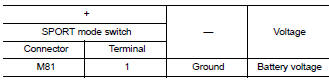
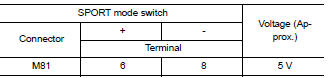
- Check the voltage between SPORT mode switch harness connector terminals.
Is the inspection result normal? Yes >> check intermittent incident. Refer to gi-39, "intermittent incident". If ok, replace sport mode switch. Refer to dms-58, "removal and installation".
No >> go to 3.
3.Check sport mode switch illumination power supply-2
Check the voltage between sport mode switch harness connector and ground.
Is the inspection result normal? Yes >> go to 6.
No >> go to 4.
4.Check fuse
- Turn off the headlamp.
- Turn ignition switch off.
- Pull out #37 fuse. Refer to pg-47, "terminal arrangement".
- Check that the fuse is not fusing.
Is the inspection result normal? YES >> GO TO 5.
NO >> Replace the fuse after repair the applicable circuit.
5.Check sport mode switch illumination power supply circuit
- Disconnect IPDM E/R harness connector E45. Refer to INL-26, "Wiring Diagram".
- Check the continuity between ipdm e/r harness connector and sport mode switch harness connector.
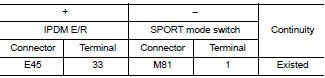
- Also check harness for short to ground.
Is the inspection result normal? Yes >> perform ipdm e/r auto active test and check tail lamp relay operation. Refer to pcs-9, "diagnosis description" (with intelligent key), pcs-37, "diagnosis description" (without intelligent key).
No >> repair or replace error-detected parts.
6.Check ground circuit
- Turn off the headlamp.
- Turn ignition switch off
- Check continuity between SPORT mode switch harness connector terminal and ground.
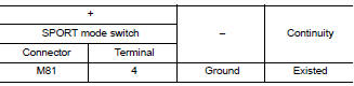
Is the inspection result normal? Yes >> check intermittent incident. Refer to gi-39, "intermittent incident".
No >> repair or replace error-detected parts.
7.Check sport mode switch circuit
- Turn off the headlamp.
- Turn ignition switch off.
- Disconnect SPORT mode switch harness connector.
- Turn ignition switch ON.
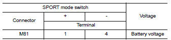
- Check voltage between sport mode switch harness connector terminals.
Is the inspection result normal? Yes >> go to 11.
No >> go to 8.
8.Check ground circuit
- Turn ignition switch off.
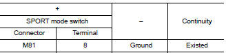
- Check the continuity between sport mode switch harness connector and ground.
Is the inspection result normal? Yes >> go to 9.
No >> repair or replace damaged parts.
9.Check circuit between combination meter and sport mode switch-1
- Disconnect combination meter harness connector m38.
- Check continuity between combination meter harness connector terminal and sport mode switch harness connector terminal.
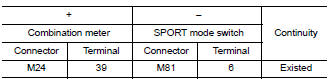
- Also check harness for short to power and short to ground.
Is the inspection result normal? Yes >> go to 10.
No >> repair or replace damaged parts.
10.Check combination meter input/output signal
- Connect all of disconnected connectors.
- Check input/output signal of combination meter. Refer to MWI-20, "Reference Value".
Is the inspection result normal? Yes >> check intermittent incident. Refer to gi-39, "intermittent incident".
No >> repair or replace error detected parts.
11.Check sport mode switch
Check sport mode switch. Refer to dms-55, "component inspection".
Is the inspection result normal? Yes >> check intermittent incident. Refer to gi-39, "intermittent incident".
No >> replace sport mode switch. Refer to dms-58, "removal and installation".
Component inspection
1.Check sport mode switch
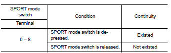
Check continuity between sport mode switch connector terminals.
Is the inspection result normal? Yes >> inspection end
No >> replace sport mode switch. Refer to dms-58, "removal and installation".
Sport mode
Component function check
1. Check sport mode operation
- Turn ignition switch ON.
- Check sport mode indicator lamp turns on/off on combination meter when turn sport mode switch on/off.
Is the inspection result normal? Yes >> inspection end.
No >> proceed to dms-57, "diagnosis procedure".
Diagnosis procedure
1.Check dtc in ecm
 With consult
Check “self diagnostic results” in “engine”.
Are any dtc detected? Yes >> check dtc detected item. Refer to ec-94, "dtc index".
No >> go to 2.
2.Check dtc in combination meter
 With consult
Check “self diagnostic results” in “meter/m&a”.
Is any dtc detected? Yes >> check dtc detected item. Refer to mwi-26, "dtc index".
No >> go to 3.
3.Check combination meter
 With consult
- Select “data monitor” in “meter/m&a”.
- Check that “sport mode ind” turns on/off when sport mode switch is operated. Refer to mwi-20, "reference value".
Is the inspection result normal? Yes >> replace combination meter. Refer to mwi-77, "removal and installation".
No >> go to 4.
4.Check sport mode switch system
Check sport mode switch system. Refer to dms-53, "component function check".
Is the inspection result normal? Yes >> inspection end
No >> repair or replace error-detected parts.
 Basic inspection
Diagnosis and repair work flow
Work flow
Overall sequence
Detailed flow
1.Get information for symptom
Get the detailed information from the customer about the symptom (the
condition and the ...
 Removal and installation
Sport mode switch
Removal and installation
Removal
Remove instrument lower panel lh. Refer to ip-21, "removal and
installation".
Remove sport mode switch.
Installation
Install ...
Other materials:
Removal and installation
Audio unit
Exploded view
Audio unit
Audio unit bracket (LH)
Audio unit bracket (rh)
Removal and installation
Removal
Disconnect the negative battery terminal. Refer to pg-50, "removal and
installation (battery)".
Remove cluster lid c lower. Refer to ip-20, "re ...
Vehicle security system (if so equipped)
The vehicle security system provides visual and
audible alarm signals if someone opens the doors
when the system is armed. It is not, however, a
motion detection type system that activates when
a vehicle is moved or when a vibration occurs.
The system helps detect vehicle theft but cannot
prev ...
C1164, C1165, C1166, C1167 CV/SV System
DTC Logic
Dtc detection logic
DTC
Display Item
Malfunction detected condition
Possible causes
C1164
CV 1
When a malfunction is detected in cut valve 1.
Harness or connector
ABS actuator and electric unit
(control unit)
Fusible link
Battery ...
