Nissan Sentra Service Manual: Diagnosis system (ipdm e/r) (without intelligent key system)
Diagnosis Description
AUTO ACTIVE TEST
Description
In auto active test, the IPDM E/R sends a drive signal to the following systems to check their operation.
- Front wiper (LO, HI)
- Parking lamp
- License plate lamp
- Tail lamp
- Front fog lamp (if equipped)
- Headlamp (LO, HI)
- A/C compressor (magnet clutch) (if equipped)
- Cooling fan
Operation Procedure
NOTE:
Never perform auto active test in the following conditions.
- Passenger door is open
- CONSULT is connected
- Close the hood and lift the wiper arms from the windshield. (Prevent windshield damage due to wiper operation)
NOTE:
When auto active test is performed with hood opened, sprinkle water on windshield beforehand.
- Turn the ignition switch OFF.
- Turn the ignition switch ON, and within 20 seconds, press the driver door switch 10 times. Then turn the ignition switch OFF.
- Turn the ignition switch ON within 10 seconds. After that the horn sounds once and the auto active test starts.
- After a series of the following operations is repeated 3 times, auto active test is completed.
NOTE:
- When auto active test has to be cancelled halfway through test, turn the ignition switch OFF.
- When auto active test is not activated, door switch may be the cause. Check door switch. Refer to DLK-255, "Component Inspection".
Inspection in Auto Active Test
When auto active test is actuated, the following operation sequence is repeated 3 times.
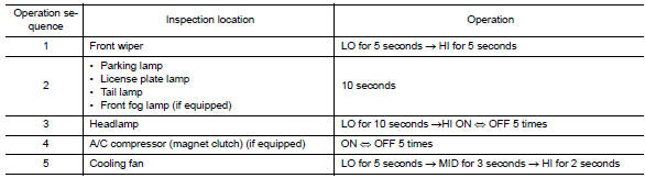
Concept of Auto Active Test
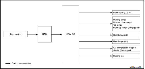
- IPDM E/R starts the auto active test with the door switch signals
transmitted by BCM via CAN communication.
Therefore, the CAN communication line between IPDM E/R and BCM is considered normal if the auto active test starts successfully.
- The auto active test facilitates troubleshooting if any systems controlled by IPDM E/R cannot be operated.
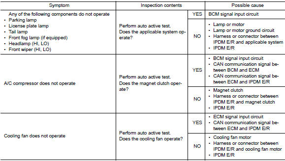
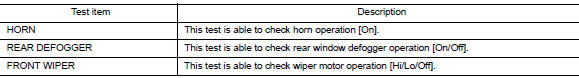
Diagnosis Chart in Auto Active Test
CONSULT Function (IPDM E/R)
APPLICATION ITEM
CONSULT performs the following functions via CAN communication with IPDM E/R.
| Direct Diagnostic Mode | Description |
| Ecu Identification | The IPDM E/R part number is displayed. |
| Self Diagnostic Result | The IPDM E/R self diagnostic results are displayed. |
| Data Monitor | The IPDM E/R input/output data is displayed in real time. |
| Active Test | The IPDM E/R activates outputs to test components. |
| CAN Diag Support Mntr | The result of transmit/receive diagnosis of CAN communication is displayed. |
ECU IDENTIFICATION
The IPDM E/R part number is displayed.
SELF DIAGNOSTIC RESULT
Refer to PCS-48, "DTC Index".
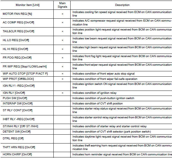
DATA MONITOR
ACTIVE TEST

CAN DIAG SUPPORT MNTR
Refer to LAN-13, "CAN Diagnostic Support Monitor".
 Diagnosis system (ipdm e/r) (with intelligent key system)
Diagnosis description
Auto active test
Description
In auto active test, the IPDM E/R sends a drive signal to the following
systems to check their operation.
Front wiper (lo, hi)
Parking lam ...
 Ecu diagnosis information
BCM, IPDM E/R
List of ECU Reference
...
Other materials:
P0443 EVAP Canister purge volume control solenoid valve
DTC No.
CONSULT screen terms
(Trouble diagnosis content)
DTC detecting condition
Possible cause
P0443
PURG VOLUME CONT/V
(Evaporative emission system
purge control valve circuit)
A
The canister purge flow is detected during
the vehicle is stopped while t ...
Ambient sensor signal circuit
Description
It detects outside air temperature and converts it into a resistance value
which is then input into the combination
meter.
Diagnosis Procedure
Regarding wiring diagram information, refer to mwi-28, "wiring diagram".
1.Check ambient sensor signal circuit
Turn igniti ...
System
VDC/TCS/ABS
VDC/TCS/ABS : System Diagram
VDC/TCS/ABS : System Description
The system switches fluid pressure of each brake caliper and
each wheel cylinder to increase, to hold, or to
decrease according to signals from control unit in ABS actuator and electric
unit (control unit) ...
