Nissan Sentra Service Manual: Ambient sensor signal circuit
Description
It detects outside air temperature and converts it into a resistance value which is then input into the combination meter.
Diagnosis Procedure
Regarding wiring diagram information, refer to mwi-28, "wiring diagram".
1.Check ambient sensor signal circuit
- Turn ignition switch off.
- Disconnect combination meter connector and ambient sensor connector.
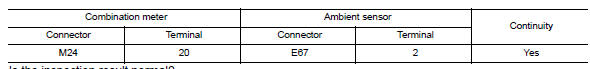
- Check continuity between combination meter harness connector and ambient sensor harness connector.

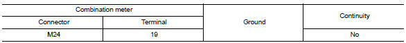
- Check continuity between combination meter harness connector and ground.
Is the inspection result normal? Yes >> go to 2.
No >> repair or replace harness or connector.
2.Check ambient sensor signal ground circuit
Check continuity between combination meter harness connector and ambient sensor harness connector.
Is the inspection result normal? YES >> Inspection End.
NO >> Repair or replace harness or connector.
Component Inspection
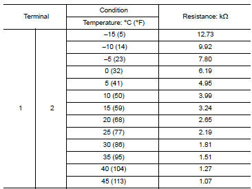
1.Check ambient sensor
- Turn ignition switch OFF.
- Disconnect ambient sensor connector.
- Check resistance between ambient sensor terminals.
Is the inspection result normal? Yes >> inspection end.
No >> replace ambient sensor. Refer to hac-106, "removal and installation".
 Parking brake switch signal circuit
Component function check
1.Check parking brake switch operation
Check that brake warning lamp in combination meter turns on/off when parking
brake is actuated.
Is the inspection result normal?
...
 A/c auto amp. Connection recognition signal circuit
Description
A/c auto amp. Transmits the a/c auto amp. Connection recognition signal to
the combination meter
Diagnosis procedure (with manual a/c)
Regarding wiring diagram information, refer to ...
Other materials:
Slip indicator lamp
Component Function Check
1.CHECK SLIP INDICATOR LAMP FUNCTION
Check that slip indicator lamp in combination meter turns ON for
approximately 2 seconds after ignition switch
is turned ON.
Is the inspection result normal?
YES >> Inspection End.
NO >> Proceed to diagnosis proce ...
P0111 IAT Sensor
DTC Logic
DTC DETECTION LOGIC
DTC No.
CONSULT screen terms
(Trouble diagnosis content)
DTC detecting condition
Possible cause
P0111
IAT SENSOR 1 B1
(Intake air temperature sensor 1
circuit range/performance bank 1)
The comparison result of signals transmitte ...
Tire pressure
Tire Pressure Monitoring System
(TPMS)
This vehicle is equipped with the Tire
Pressure Monitoring System (TPMS). It
monitors tire pressure of all tires except
the spare. When the low tire pressure
warning light is lit and the CHECK TIRE
PRES warning is displayed in the odometer,
one or more ...
