Nissan Sentra Service Manual: A/c auto amp. Connection recognition signal circuit
Description
A/c auto amp. Transmits the a/c auto amp. Connection recognition signal to the combination meter
Diagnosis procedure (with manual a/c)
Regarding wiring diagram information, refer to mwi-28, "wiring diagram".
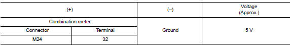
1.Check a/c auto amp. Connection recognition signal
- Turn ignition switch on.
- Check voltage between combination meter harness connector and ground.
Is the inspection result normal? Yes >> inspection end.
No >> go to 2.
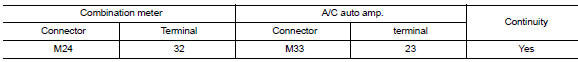
2.Check a/c auto amp. Connection recognition signal circuit
- Turn ignition switch OFF.
- Disconnect combination meter connector and a/c auto amp. Connector.
- Check continuity between combination meter harness connector and a/c auto amp. Harness connector.
- Check continuity between combination meter harness connector and ground.
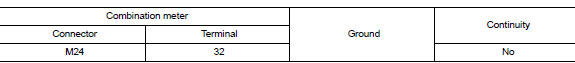
Is the inspection result normal? Yes >> inspection end.
No >> repair or replace harness or connector.
 Ambient sensor signal circuit
Description
It detects outside air temperature and converts it into a resistance value
which is then input into the combination
meter.
Diagnosis Procedure
Regarding wiring diagram information, ...
 Washer fluid level switch circuit
Description
Transmits the washer level switch signal to the combination meter.
Diagnosis procedure
Regarding Wiring Diagram information, refer to MWI-28, "Wiring Diagram".
1.Check wash ...
Other materials:
B terminal circuit
Description
“B” terminal circuit supplies power to charge the battery and to operate the
vehicles electrical system.
Diagnosis procedure
Regarding wiring diagram information. Refer to chg-9, "wiring diagram".
1.Check “b” terminal connection
Turn ignition switc ...
Locking with key
Driver’s side
The power door lock system allows you to lock or
unlock all doors at the same time.
Turning the key toward the front 1 of the vehicle
locks all doors.
Turning the key one time toward the rear 2 of the
vehicle unlocks that door. From that position,
returning the key to ...
Windshield glass
Exploded View
Windshield glass molding
Spacer
Rubber dam
Windshield glass
Windshield insulator
Front pillar finisher
Instrument panel
Cowl top cover
Roof panel
Cowl top
Body side outer
Headlining
Adhesive
12 +2.0 mm (0.5 +0.08 in)
7 +2.0 mm (0.3 +0.08 in)
...
