Nissan Sentra Service Manual: Washer fluid level switch circuit
Description
Transmits the washer level switch signal to the combination meter.
Diagnosis procedure
Regarding Wiring Diagram information, refer to MWI-28, "Wiring Diagram".
1.Check washer level switch signal circuit
- Turn ignition switch off.
- Disconnect combination meter connector and washer fluid level switch connector.
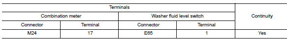
- Check continuity between combination meter harness connector and washer fluid level switch harness connector.
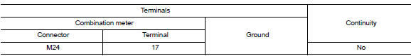
- Check continuity between combination meter harness connector and ground.
Is the inspection result normal? YES >> GO TO 2.
NO >> Repair or replace harness or connector.
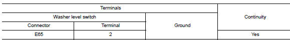
2.Check washer fluid level switch ground circuit
Check continuity between washer fluid level switch connector and ground.
Is the inspection result normal? YES >> Inspection End.
NO >> Repair or replace harness or connector.
Component inspection
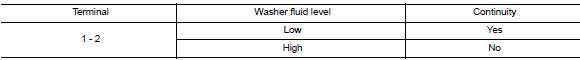
1.Check washer fluid level switch
Check continuity between washer fluid level switch terminals 1 and 2.
Is the inspection result normal?
Yes >> inspection end.
No >> replace washer fluid level switch.Refer to ww-53, "removal and installation".
 A/c auto amp. Connection recognition signal circuit
Description
A/c auto amp. Transmits the a/c auto amp. Connection recognition signal to
the combination meter
Diagnosis procedure (with manual a/c)
Regarding wiring diagram information, refer to ...

Other materials:
Forward-facing child restraint installation using the seat belts
WARNINGThe three-point seat belt with Automatic
Locking Retractor (ALR) must be used
when installing a child restraint. Failure to
use the ALR mode will result in the child
restraint not being properly secured. The
restraint could tip over or be loose and
cause injury to a c ...
Mixture ratio self-learning value
clear
Description
This describes how to erase the mixture ratio self-learning value. For the
actual procedure, follow the instructions
in “Diagnosis Procedure”.
Work Procedure
1.START
With CONSULT
Start engine and warm it up to normal operating temperature.
Select “SELF-LEARNI ...
Precaution
Precaution for Supplemental Restraint System (SRS) "AIR BAG" and "SEAT
BELT PRE-TENSIONER"
The Supplemental Restraint System such as “AIR BAG” and “SEAT BELT PRE-TENSIONER”,
used along
with a front seat belt, helps to reduce the risk or severity of injur ...
