Nissan Sentra Service Manual: P0715 Input speed sensor A
DTC Logic
DTC DETECTION LOGIC
|
DTC |
CONSULT screen terms (Trouble diagnosis content) |
DTC detection condition |
Possible causes |
| P0715 | INPUT SPEED SENSOR A (Input/Turbine Speed Sensor A Circuit) | The primary speed sensor value is less than
150 rpm continuously for 5 seconds or more
under the following diagnosis conditions: Diagnosis conditions
|
|
| The primary speed sensor value is 240 rpm or
less continuously for 500 msec or more under
the following diagnosis conditions: Diagnosis conditions
|
DTC CONFIRMATION PROCEDURE
CAUTION:
Be careful of the driving speed.
1.PREPARATION BEFORE WORK
If another “DTC CONFIRMATION PROCEDURE” occurs just before, turn ignition switch OFF and wait for at least 10 seconds, then perform the next test.
>> GO TO 2.
2.CHECK DTC DETECTION
- Start the engine.
- Drive the vehicle.
- Maintain the following conditions for 10 seconds or more.
Selector lever : “L” POSITION
Vehicle speed : 40 km/h (25 MPH) or more
- Stop the vehicle.
- Check the first trip DTC.
Is “P0715” detected? YES >> Go to TM-178, "Diagnosis Procedure".
NO >> INSPECTION END
Diagnosis Procedure
1.CHECK PRIMARY SPEED SENSOR POWER CIRCUIT
- Turn ignition switch OFF.
- Disconnect primary speed sensor connector.
- Turn ignition switch ON.
- Check voltage between primary speed sensor harness connector terminal and ground.
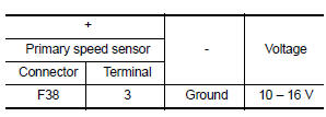
Is the check result normal? YES >> GO TO 2.
NO >> GO TO 6.
2.CHECK PRIMARY SPEED SENSOR GROUND CIRCUIT
Check continuity between primary speed sensor harness connector terminal and ground.
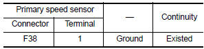
Is the check result normal? YES >> GO TO 3.
NO >> Repair or replace malfunctioning parts
3.CHECK CIRCUIT BETWEEN PRIMARY SPEED SENSOR AND TCM (PART 1)
- Turn ignition switch OFF.
- Disconnect TCM connector.
- Check continuity between primary speed sensor harness connector terminal and TCM harness connector terminal.
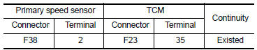
Is the check result normal? YES >> GO TO 4.
NO >> Repair or replace malfunctioning parts.
4.CHECK CIRCUIT BETWEEN PRIMARY SPEED SENSOR AND TCM (PART 2)
Check continuity between primary speed sensor harness connector terminal and ground.
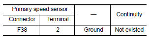
Is the check result normal? YES >> GO TO 5.
NO >> Repair or replace malfunctioning parts.
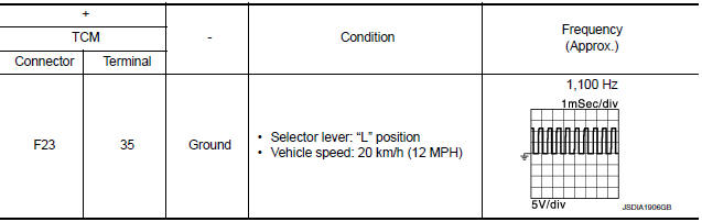
5.Check TCM Input signals
- Connect all of disconnected connectors.
- Lift the vehicle.
- Start the engine.
- Check frequency of primary speed sensor.
Is the check result normal? YES >> Check intermittent incident. Refer to GI-39, "Intermittent Incident".
NO >> Replace primary speed sensor. Refer to TM-268, "Removal and Installation".
6.DETECT MALFUNCTIONING ITEMS
Check the following items:
- Harness open circuit or short circuit between the ignition switch and IPDM E/R. Refer to PG-20, "Wiring Diagram — Ignition Power Supply —".
- Harness open circuit or short circuit between IPDM E/R and primary speed sensor.
- 10A fuse (No.45, IPDM E/R). Refer to PG-49, "IPDM E/R Terminal Arrangement".
- IPDM E/R
Is the check result normal? YES >> Check intermittent incident. Refer to GI-39, "Intermittent Incident".
NO >> Repair or replace malfunctioning parts.
 P0713 Transmission fluid temperature sensor A
DTC Logic
DTC DETECTION LOGIC
DTC
CONSULT screen terms
(Trouble diagnosis content)
DTC detection condition
Possible causes
P0713
FLUID TEMP SENSOR A
(Transmission ...
 P0720 Output speed sensor
DTC Logic
DTC DETECTION LOGIC
DTC
CONSULT screen terms
(Trouble diagnosis content)
DTC detection condition
Possible causes
P0720
OUTPUT SPEED SENSOR
(Output Speed ...
Other materials:
Differential side oil seal
Exploded View
Transaxle assembly
Differential side oil seal (left side)
Differential side oil seal (right side)
: Vehicle front
: Always replace after every
disassembly.
: Genuine NISSAN CVT Fluid NS-3
Removal and Installation
REMOVAL
NOTE:
Cap or plug openings to prevent f ...
Front seat belt
Exploded View
D-ring anchor
Seat belt height adjuster cover
Seat belt buckle
Seat belt retractor
Seat belt height adjuster
Lap belt pre-tensioner harness
connector
Shoulder belt pre-tensioner
harness connector
Front
NOTE:
LH side shown; RH side similar.
Removal an ...
Read first—then drive safely
FOREWORD
Welcome to the growing family of new NISSAN
owners. This vehicle is delivered to you with
confidence. It was produced using the latest
techniques and strict quality control.
This manual was prepared to help you understand
the operation and maintenance of your
vehicle so that you ma ...
