Nissan Sentra Service Manual: P0713 Transmission fluid temperature sensor A
DTC Logic
DTC DETECTION LOGIC
| DTC | CONSULT screen terms (Trouble diagnosis content) | DTC detection condition | Possible causes |
| P0713 | FLUID TEMP SENSOR A (Transmission Fluid Temperature Sensor A Circuit High) | The CVT fluid temperature identified by the
TCM is −40В°C (−40В°F) or less continuously for
5 seconds or more under the following diagnosis
conditions: Diagnosis conditions
|
|
DTC CONFIRMATION PROCEDURE
1.PREPARATION BEFORE WORK
If another “DTC CONFIRMATION PROCEDURE” occurs just before, turn ignition switch OFF and wait for at least 10 seconds, then perform the next test.
>> GO TO 2.
2.PERFORM DTC CONFIRMATION PROCEDURE
- Start the engine.
- Maintain the following condition for 10 seconds or more.
Vehicle speed : 20 km/h (12 MPH) or more
- Stop the vehicle.
- Check the first trip DTC.
Is “P0713” detected? YES >> Go to TM-176, "Diagnosis Procedure".
NO >> INSPECTION END
Diagnosis Procedure
1.CHECK CIRCUIT BETWEEN TCM AND CVT UNIT (PART 1)
- Turn ignition switch OFF.
- Disconnect TCM connector and CVT unit connector.
- Check continuity between TCM harness connector terminals and CVT unit harness connector terminals.
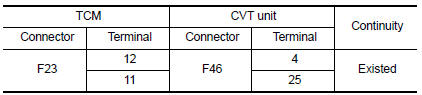
Is the inspection result normal? YES >> GO TO 2.
NO >> Repair or replace malfunctioning part.
2.CHECK CIRCUIT BETWEEN TCM AND CVT UNIT (PART 2)
- Turn ignition switch ON.
- Check voltage between TCM harness connector terminal and ground.
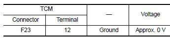
Is the inspection result normal? YES >> GO TO 3.
NO >> Repair or replace malfunctioning part.
3.CHECK CVT FLUID TEMPERATURE SENSOR
Check CVT fluid temperature sensor. Refer to TM-177, "Component Inspection".
Is the inspection result normal? YES >> Check intermittent incident. Refer to GI-39, "Intermittent Incident".
NO >> Repair or replace malfunctioning parts.
Component Inspection
1.CHECK CVT FLUID TEMPERATURE SENSOR
Check resistance between CVT unit connector terminals.
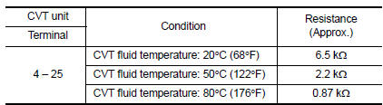
Is the inspection result normal? YES >> INSPECTION END
NO >> There is a malfunction of CVT fluid temperature sensor. Replace transaxle assembly. Refer to TM-283, "Removal and Installation".
 P0712 Transmission fluid temperature sensor A
DTC Logic
DTC DETECTION LOGIC
DTC
CONSULT screen terms
(Trouble diagnosis content)
DTC detection condition
Possible causes
P0712
FLUID TEMP SENSOR A
(Transmission F ...
 P0715 Input speed sensor A
DTC Logic
DTC DETECTION LOGIC
DTC
CONSULT screen terms
(Trouble diagnosis content)
DTC detection condition
Possible causes
P0715
INPUT SPEED SENSOR A
...
Other materials:
P0138 HO2S2
DTC Logic
DTC DETECTION LOGIC
The heated oxygen sensor 2 has a much longer switching time between rich and
lean than the air fuel ratio (A/
F) sensor 1. The oxygen storage capacity of the three way catalyst (manifold)
causes the longer switching
time.
MALFUNCTION A
To judge the malfunction ...
Parking lamp circuit
Description
The ipdm e/r (intelligent power distribution module engine room) controls the
tail lamp relay based on inputs
from the bcm over the can communication lines. When the tail lamp relay is
energized, power flows through
fuse 36, located in the ipdm e/r. Power then flows to the front ...
ID registration cannot be completed
Diagnosis Procedure
NOTE:
The Signal Tech II Tool (J-50190) can be used to perform the following
functions. Refer to the Signal Tech II
User Guide for additional information.
Activate and display TPMS transmitter IDs
Display tire pressure reported by the TPMS transmitter
Read TPMS DTCs
...
