Nissan Sentra Service Manual: Parking lamp circuit
Description
The ipdm e/r (intelligent power distribution module engine room) controls the tail lamp relay based on inputs from the bcm over the can communication lines. When the tail lamp relay is energized, power flows through fuse 36, located in the ipdm e/r. Power then flows to the front and rear combination lamps, license plate lamps.
Component function check
1.Check parking lamp operation
 Without consult
- Activate ipdm e/r auto active test. Refer to exl-24, "diagnosis description" (with intelligent key system) or exl-28, "diagnosis description" (without intelligent key system).
- Check that the parking lamp is turned on.
 Without consult
- Select external lamp of ipdm e/r active test item
- While operating the test items, check that the parking lamp is turned on.
Tail : parking lamp on
Off : parking lamp off
Is the inspection result normal? Yes >> parking lamp circuit is normal.
No >> refer to exl-96, "diagnosis procedure".
Diagnosis procedure
Regarding wiring diagram information, refer to exl-68, "wiring diagram".
1.Check parking lamp fuses
- Turn the ignition switch off.
- Check that the following fuses are not blown.

Is the fuse blown? Yes >> replace the blown fuse after repairing the affected circuit.
No >> go to 2.
2.Check tail lamp relay output (voltage)
- Disconnect the front or rear combination lamp connector or license plate lamp connector in question.
- Turn the ignition switch on.
- Turn the parking lamps on.
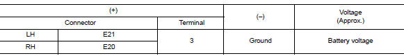
- With the parking lamps on, check voltage between the front combination lamp front (parking) connector and ground.
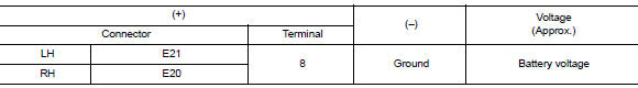
- With the parking lamps ON, check voltage between the front combination lamp (side marker) connector and ground.
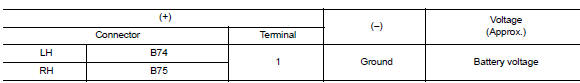
- With the parking lamps on, check voltage between the rear combination lamp connector and ground.

- With the parking lamps on, check voltage between the license plate lamp connector and ground.
Are the inspection results normal? Yes >> go to 4.
No >> go to 3.
3.Check parking lamp circuit (open)
- Turn the ignition switch off.
- Disconnect ipdm e/r connector.
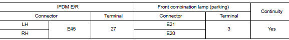
- Check continuity between the ipdm e/r harness connector and the front combination lamp (parking) harness connector.
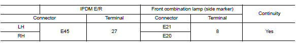
- Check continuity between the ipdm e/r harness connector and the front combination lamp (side marker) harness connector.
- Check continuity between the ipdm e/r harness connector and the rear combination lamp harness connector.


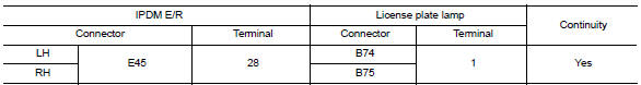
- Check continuity between the ipdm e/r harness connector and license plate lamp connector.
Are the inspection results normal? Yes >> replace ipdm e/r. Refer to pcs-30, "removal and installation" (with intelligent key system) or pcs-58, "removal and installation" (without intelligent key system).
No >> repair or replace the harness or connector.
4.Check parking lamp ground circuits
- Check continuity between the front combination lamp (parking) harness connector and ground.
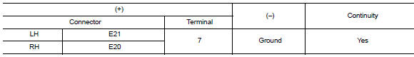
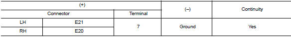
- Check continuity between the front combination lamp (side marker) harness connector and ground.
- Check continuity between the rear combination lamp harness connector and ground.
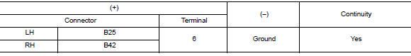
- Check continuity between the license plate lamp harness connector and ground.
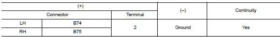
Are the inspection results normal? Yes >> inspect the parking lamp bulb.
No >> repair or replace the harness or connector.
 Front fog lamp circuit
Description
The ipdm e/r (intelligent power distribution module engine room) controls the
front fog lamp relay based on
inputs from the bcm over the can communication lines. When the front fog lam ...
 Turn signal lamp circuit
Description
The bcm monitors inputs from the combination switch to determine when to
activate the turn signals. The
bcm outputs voltage direction to the left and right turn signals during turn
...
Other materials:
Trip computer
When the ignition switch is placed in the ON
position, the modes of the trip
computer can be
selected by pressing the button on the
steering wheel. The following modes can be selected:
Trip A
Trip B
ECO Pedal Indicator
Instant fuel economy
Average fuel economy
Average speed
Dis ...
Water outlet
Exploded View
CVT MODELS
Water control valve
Rubber ring
Radiator hose (upper)
Clamp
Water outlet
CVT oil warmer hose (outlet)
Heater hose (inlet)
Heater hose (outlet)
Electric throttle control actuator hose
(outlet)
Electric throttle control actuator hose
(inlet)
E ...
Description
Number
Item
Description
1
Power supply
This means the power supply of fusible link or fuse.
2
Fusible link
“X” means the fusible link.
3
Number of fusible link/
fuse
This means the numbe ...
