Nissan Sentra Service Manual: Turn signal lamp circuit
Description
The bcm monitors inputs from the combination switch to determine when to activate the turn signals. The bcm outputs voltage direction to the left and right turn signals during turn signal operation or both during hazard warning operation. The bcm sends a turn signal indicator request to the combination meter via the can communication lines.
The bcm performs the fast flasher operation (fail-safe) if any bulb or harness of the turn signal lamp circuit is open.
Note:
Turn signal lamp blinks at normal speed when using the hazard warning lamp.
Component function check
1.Check turn signal lamp
 Consult
- Select FLASHER of BCM (FLASHER) active test item.
- With operating the test items, check that the turn signal lamp blinks.
Lh : turn signal lamps (lh) on
Rh : turn signal lamps (rh) on
Off : the turn signal lamps off
Does the turn signal lamp blink? Yes >> turn signal lamp circuit is normal.
No >> refer to exl-99, "diagnosis procedure".
Diagnosis procedure
Regarding wiring diagram information, refer to exl-58, "wiring diagram".
1.Check turn signal lamp bulb
Check the applicable lamp bulb to be sure the proper bulb standard is in use and the bulb is not open.
Is the bulb ok? Yes >> go to 2.
No >> replace the bulb.
2.Check turn signal lamp output voltage
- Turn the ignition switch off.
- Disconnect the front or rear combination lamp harness connector or the door mirror harness connector (if equipped with turn signal in mirror) in question.
- Turn the ignition switch on.
- Operate the turn signal switch.
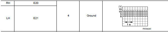
- While the turn signal is operating, check the voltage between the front combination lamp harness connector and ground.
![]()
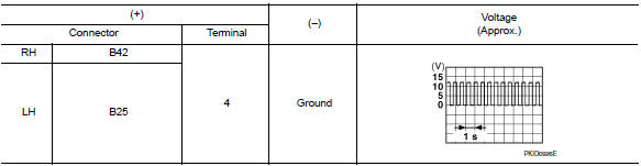
- While the turn signal is operating, check the voltage between the rear combination lamp harness connector and ground.
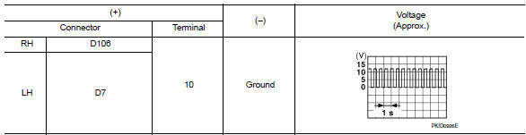
- While the turn signal is operating, check the voltage between the door mirror harness connector and ground.
Is the inspection result normal? Yes >> go to 5.
No >> go to 3.
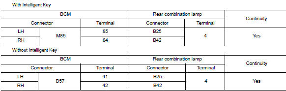
3.Check turn signal lamp circuit for open
- Turn the ignition switch off.
- Disconnect bcm harness connector in question.
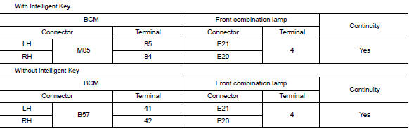
- Check continuity between the bcm harness connector and the front combination lamp harness connector.
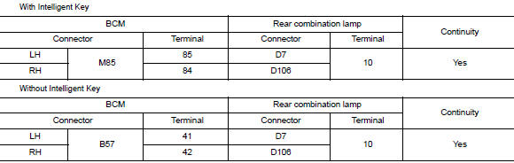
- Check continuity between the BCM harness connector and the rear combination lamp harness connector.
- Check continuity between the BCM harness connector and the door mirror harness connector in question.
Is the inspection results normal? YES >> GO TO 4.
NO >> Repair or replace the harness or connectors.
4.Check turn signal lamp short circuit
- Check continuity between the bcm harness connector and ground.
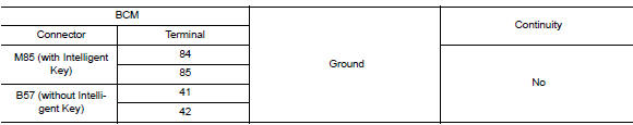
Are the inspection results normal? YES >> Replace BCM. Refer to BCS-73, "Removal and Installation" (with Intelligent Key system) or BCS- 126, "Removal and Installation" (without Intelligent Key system).
NO >> Repair or replace the harness or connectors.
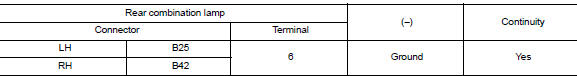
5.Check turn signal lamp ground circuit
- Turn the ignition switch OFF.
- Check continuity between the front combination lamp harness connector or the rear combination lamp harness connector or the door mirror harness connector in question and ground.


- Check continuity between the rear combination lamp harness connector and ground.
- Check continuity between the door mirror harness connector and ground.
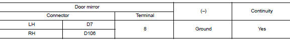
Are the inspection results normal? YES >> Replace the malfunctioning lamp.
NO >> Repair or replace the harness or connectors.
 Parking lamp circuit
Description
The ipdm e/r (intelligent power distribution module engine room) controls the
tail lamp relay based on inputs
from the bcm over the can communication lines. When the tail lamp relay i ...
 Optical sensor
Description
The optical sensor measures ambient light and transmits the optical sensor
signal to the bcm.
Component function check
1.Check optical sensor signal by consult
Consult
Turn the ...
Other materials:
Symptom diagnosis
The sport mode indicator lamp does not turn on
Description
The sport mode indicator lamp does not turn on when the sport mode switch is
operated.
Diagnosis procedure
1.Perform combination meter on board diagnosis
Perform combination meter on board diagnosis. Refer to mwi-16, "descriptio ...
Vehicle Dynamic Control (VDC) system
The Vehicle Dynamic Control (VDC) system uses
various sensors to monitor driver inputs and vehicle
motion. Under certain driving conditions,
the VDC System helps to perform the following
functions:
Controls brake pressure to reduce wheel
slip on one slipping drive wheel so power is
trans ...
NISSAN vehicle immobilizer system (if so equipped)
The NISSAN Vehicle Immobilizer System will not
allow the engine to start without the use of a
registered key.
If the engine fails to start using a registered key
(for example, when interference is caused by
another registered key, an automated toll road
device or automatic payment device on ...
