Nissan Sentra Service Manual: Optical sensor
Description
The optical sensor measures ambient light and transmits the optical sensor signal to the bcm.
Component function check
1.Check optical sensor signal by consult
 Consult
- Turn the ignition switch ON.
- Select opti sen of bcm (head lamp) data monitor item.
- Turn the lighting switch to AUTO.
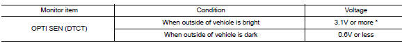
*: Illuminates the optical sensor. The value may be less than the standard value if brightness is weak.
Is the inspection result normal? YES >> Optical sensor is normal.
NO >> Refer to EXL-103, "Diagnosis Procedure".
Diagnosis procedure
Regarding Wiring Diagram information, refer to EXL-53, "Wiring Diagram".
1.Check optical sensor power supply input
- Turn the ignition switch off
- Disconnect the optical sensor harness connector.
- Turn the ignition switch ON.
- Turn the lighting switch to auto.
- Check the voltage between the optical sensor harness connector and ground.
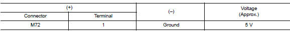
Is the inspection result normal? Yes >> go to 2.
No >> go to 3.
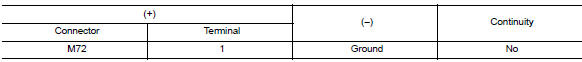
2.Check optical sensor ground circuit
- Turn the ignition switch off.
- Check continuity between the optical sensor harness connector and ground.
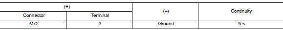
Is the inspection result normal? YES >> GO TO 4.
NO >> GO TO 5.
3.Check optical sensor power supply for open circuit
- Turn the ignition switch off.
- Disconnect the bcm harness connector.
- Check continuity between optical sensor harness connector and bcm harness connector.
- Check continuity between optical sensor harness connector and ground.
Is the inspection result normal? Yes >> replace bcm. Refer to bcs-73, "removal and installation".
No >> repair or replace the harness or connectors.
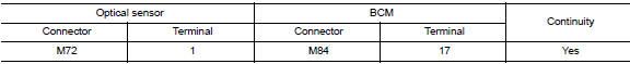
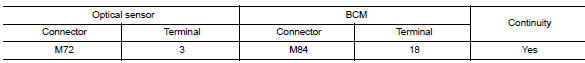
4.Check optical sensor signal open circuit
- Disconnect optical sensor connector and bcm connector.
- Check continuity between optical sensor harness connector and bcm harness connector.
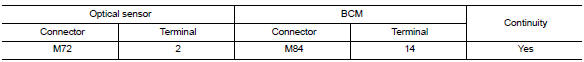
- Check continuity between optical sensor harness connector and ground.

Is the inspection result normal? Yes >> replace the optical sensor. Refer to exl-130, "removal and installation".
No >> repair or replace harness or connectors.
5.Check optical sensor ground for open circuit
- Disconnect the bcm harness connector.
- Check continuity between optical sensor harness connector and bcm harness connector.
Is the inspection result normal? YES >> Replace BCM. Refer to BCS-73, "Removal and Installation".
NO >> Repair or replace harness or connector.
 Turn signal lamp circuit
Description
The bcm monitors inputs from the combination switch to determine when to
activate the turn signals. The
bcm outputs voltage direction to the left and right turn signals during turn
...
 Hazard switch
Component function check
1.Check hazard switch signal by consult
Consult data monitor
Turn ignition switch ON.
Select hazard sw of bcm (flasher) data monitor item.
While operating the hazar ...
Other materials:
ECU diagnosis information
Diagnosis sensor unit
DTC Index
DIAGNOSTIC CODE CHART
NOTE:
Follow the procedures in numerical order when repairing malfunctioning
parts. Confirm whether malfunction is
eliminated using air bag warning lamp or CONSULT each time repair is finished.
If malfunction is still
observed, proceed ...
Diagnosis system (BCM) (without intelligent key system)
Common item
Common item : consult function (bcm - common item)
APPLICATION ITEM
CONSULT performs the following functions via CAN communication with BCM.
Direct Diagnostic Mode
Description
ECU identification
The BCM part number is displayed.
Self Diagnostic Result
...
Battery current sensor
Exploded view
Battery current sensor
Current sensor harness connector
Removal and installation
Removal
Loosen the battery terminal nut and disconnect battery negative
terminal. Refer to PG-50, "Exploded
View".
Disconnect the harness connector from current sensor.
...
