Nissan Sentra Service Manual: ECU diagnosis information
Diagnosis sensor unit
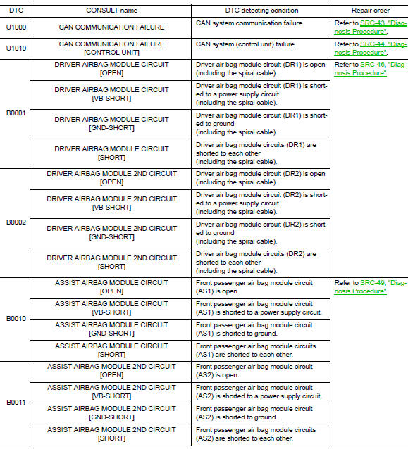
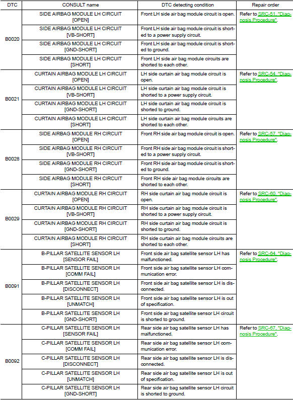
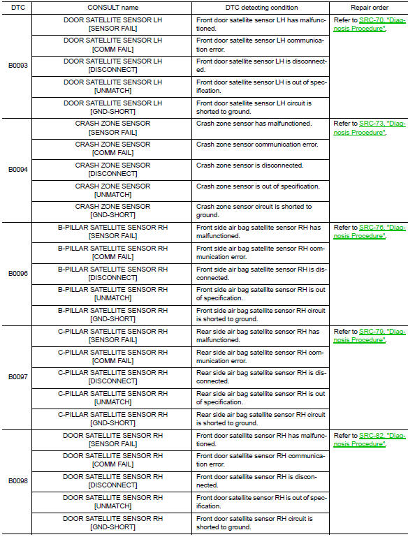
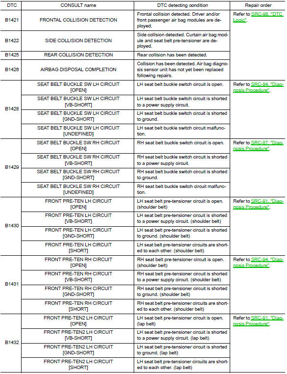
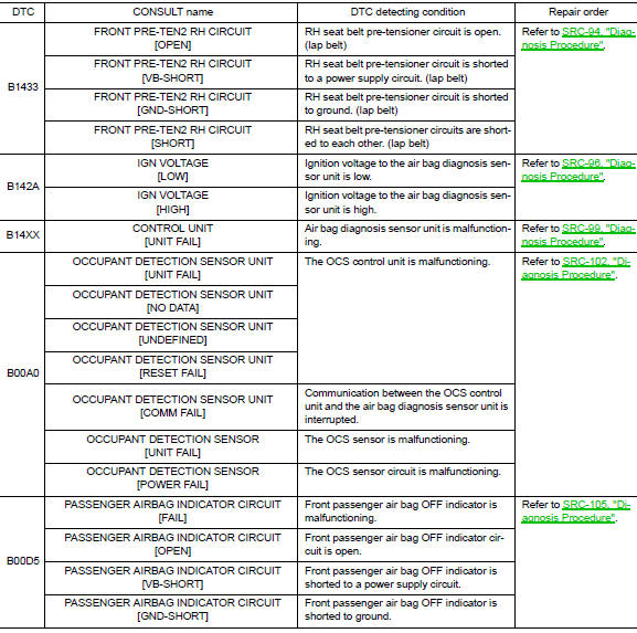
DTC Index
DIAGNOSTIC CODE CHART
NOTE:
Follow the procedures in numerical order when repairing malfunctioning parts. Confirm whether malfunction is eliminated using air bag warning lamp or CONSULT each time repair is finished. If malfunction is still observed, proceed to the next step. When malfunction is eliminated, further repair work is not required.
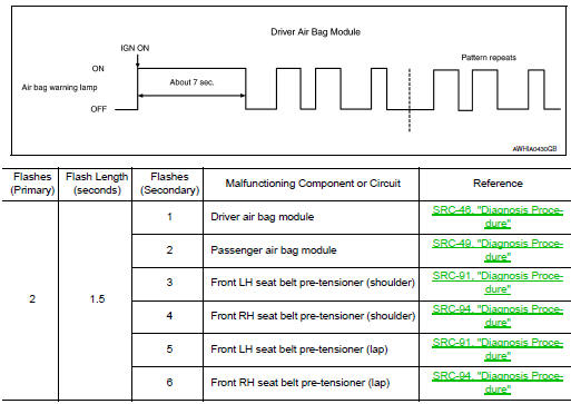
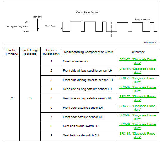
Flash Code Index
WARNING LAMP FLASH CODE CHART
How to read flash codes
- Put the vehicle in Diagnosis Mode. Refer to SRC-17, "Trouble Diagnosis without CONSULT".
- All codes are proceded by a seven second ”holding” flash.
- Identify how many primary flashes are displayed as well as the length of each primary flash.
- Refer to the tables and examples below to determine which SRS subsystem the code belongs to.
- Count the short secondary flashes that follow the primary flashes.
- Match the correct flashing pattern to the malfunctioning component and perform the Diagnosis Procedure.
Refer to the illustrations below for an example of each flashing pattern.
Front subsystem
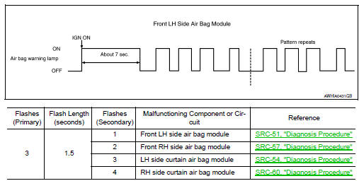
Side subsystem
Air bag subsystem
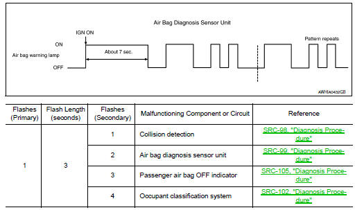
Sensor subsystem
 Diagnosis system (AIR BAG)
Description
CAUTION:
Never use electrical test equipment on any circuit related to the
SRS unless instructed in this Service
Manual. SRS wiring harnesses can be identified by yellow and/or o ...
 Wiring diagram
SRS AIR BAG SYSTEM
Wiring Diagram
...
Other materials:
Diagnosis system (ipdm e/r) (without intelligent key system)
Diagnosis Description
AUTO ACTIVE TEST
Description
In auto active test, the IPDM E/R sends a drive signal to the following
systems to check their operation.
Front wiper (LO, HI)
Parking lamp
License plate lamp
Tail lamp
Front fog lamp (if equipped)
Headlamp (LO, HI)
A/C compress ...
P2096, P2097 A/F Sensor 1
DTC Logic
DTC DETECTION LOGIC
DTC No.
CONSULT screen terms
(Trouble diagnosis content)
DTC detecting condition
Possible Cause
P2096
POST CAT FUEL TRIM SYS B1
(Post catalyst fuel trim system
too lean bank 1)
The output voltage computed by ECM from the
A/F ...
Front wiper motor ground circuit
Diagnosis procedure
Regarding Wiring Diagram information, refer to WW-24, "Wiring Diagram - With
Intelligent Key" or WW-29,
"Wiring Diagram - Without Intelligent Key".
1.Check front wiper motor (gnd) open circuit
Turn the ignition switch OFF.
Disconnect front wiper mot ...
