Nissan Sentra Service Manual: P2096, P2097 A/F Sensor 1
DTC Logic
DTC DETECTION LOGIC
| DTC No. | CONSULT screen terms (Trouble diagnosis content) | DTC detecting condition | Possible Cause |
| P2096 | POST CAT FUEL TRIM SYS B1 (Post catalyst fuel trim system too lean bank 1) | The output voltage computed by ECM from the A/F sensor 1 signal is shifts to the lean side for a specified period. |
|
| P2097 | POST CAT FUEL TRIM SYS B1 (Post catalyst fuel trim system too rich bank 1) | The A/F signal computed by ECM from the A/F sensor 1 signal is shifts to the rich side for a specified period. |
DTC CONFIRMATION PROCEDURE
1.PRECONDITIONING
If DTC Confirmation Procedure has been previously conducted, always perform the following procedure before conducting the next test.
- Turn ignition switch OFF and wait least 10 seconds.
- Turn ignition switch ON.
- Turn ignition switch OFF and wait least 10 seconds.
TESTING CONDITION:
Before performing the following procedure, confirm that battery voltage is more than 11 at idle.
>> GO TO 2.
2.PERFORM DTC CONFIRMATION PROCEDURE
- Clear the mixture ratio self-learning value. Refer to EC-142, "Work Procedure".
- Turn ignition switch OFF and wait at least 10 seconds.
- Start engine and keep the engine speed between 3,500 and 4,000 rpm for 1 minute under no load.
- Let engine idle for 1 minute.
- Keep engine speed between 2,500 and 3,000 rpm for 20 minutes.
- Check 1st trip DTC.
Is 1st trip DTC detected? YES >> Proceed to EC-419, "Diagnosis Procedure".
NO >> INSPECTION END
Diagnosis Procedure
1.CHECK HARNESS CONNECTOR
- Turn ignition switch OFF.
- Disconnect A/F sensor 1 harness connector.
- Check harness connector for water.
Water should not exit.
Is the inspection result normal? YES >> GO TO 2.
NO >> Repair or replace harness connector.
2.RETIGHTEN A/F SENSOR 1 AND HEATED OXYGEN SENSOR 2
Loosen and retighten the A/F sensor 1 and heated oxygen sensor 2. Refer to EM-30, "Exploded View", EX-5, "Exploded View".
>> GO TO 3.
3.CHECK FOR EXHAUST GAS LEAK
- Start engine and run it at idle.
- Listen for an exhaust gas leak before the three way catalyst 2.
Is exhaust gas leak detected? YES >> Repair or replace malfunctioning parts.
NO >> GO TO 4.
4.CHECK FOR INTAKE AIR LEAK
- Reconnect A/F sensor 1 harness connector.
- Start engine and run it at idle.
- Listen for an intake air leak after the mass air flow sensor.
Is intake air leak detected? YES >> Repair or replace malfunctioning parts.
NO >> GO TO 5.
5.CLEAR THE MIXTURE RATIO SELF-LEARNING VALUE
- Clear the mixture ratio self-learning value. Refer to EC-142, "Work Procedure".
- Run engine for at least 10 minutes at idle speed.
Is the 1st trip DTC P0171 or P0172 detected? Is it difficult to start engine? YES >> Perform trouble diagnosis for DTC P0171 or P0172. Refer to EC-246, "DTC Logic" or EC-250, "DTC Logic".
NO >> GO TO 6.
6.CHECK A/F SENSOR 1 POWER SUPPLY
- Turn ignition switch OFF.
- Disconnect A/F sensor 1 harness connector.
- Turn ignition switch ON.
- Check the voltage between A/F sensor 1 harness connector and ground.
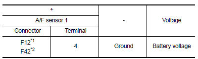
*1: Except California
*2: For California
Is the inspection result normal? YES >> GO TO 8.
NO >> GO TO 7.
7.CHECK A/F SENSOR 1 POWER SUPPLY CIRCUIT
- Turn ignition switch OFF
- Disconnect IPDM E/R harness connector.
- Check the continuity between A/F sensor 1 harness connector and IPDM E/R harness connector.
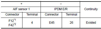
*1: Except California
*2: For California
- Also check harness for short to ground.
Is the inspection result normal? YES >> Perform the trouble diagnosis for power supply circuit.
NO >> Repair or replace error-detected parts.
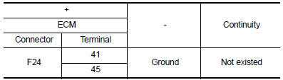
8.CHECK A/F SENSOR 1 INPUT SIGNAL CIRCUIT
- Turn ignition switch OFF.
- Disconnect ECM harness connector.
- Check the continuity between A/F sensor 1 harness connector and ECM harness connector.
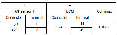
*1: Except California
*2: For California
- Check the continuity between A/F sensor 1 harness connector and ground, or ECM harness connector and ground.
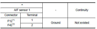
*1: Except California
*2: For California
- Also check harness for short to power.
Is the inspection result normal? YES >> GO TO 9.
NO >> Repair or replace error-detected parts.
9.CHECK A/F SENSOR 1 HEATER
Check the A/F sensor 1 heater. Refer to EC-177, "Component Inspection (A/F Sensor 1 Heater)".
Is the inspection result normal? YES >> GO TO 10.
NO >> GO TO 12.
10.CHECK HEATED OXYGEN SENSOR 2
Check heated oxygen sensor 2. Refer to EC-223, "Component Inspection (HO2S2)".
Is the inspection result normal? YES >> GO TO 11.
NO >> Replace heated oxygen sensor 2. Refer to EX-5, "Exploded View".
11.CHECK INTERMITTENT INCIDENT
Perform GI-39, "Intermittent Incident".
Is the inspection result normal?
YES >> GO TO 12.
NO >> Repair or replace error-detected parts.
12.REPLACE AIR FUEL RATIO (A/F) SENSOR 1
Replace air fuel ratio (A/F) sensor 1. Refer to EM-30, "Exploded View".
CAUTION:
- Discard any sensor which has been dropped from a height of more than 0.5 m (19.7 in) onto a hard surface such as a concrete floor; use a new one.
- Before installing new sensor, clean exhaust system threads using Oxygen Sensor Thread Cleaner [commercial service tool (J-43897-18 or J-43897-12)] and approved Anti-seize Lubricant (commercial service tool).
Do you have CONSULT? YES >> GO TO 13.
NO >> GO TO 14.
13.CONFIRM A/F ADJUSTMENT DATA
 With CONSULT
- Turn ignition switch ON.
- Select “A/F ADJ-B1” in “DATA MONITOR” mode of “ENGINE” using CONSULT.
- Make sure that “0.000” is displayed on CONSULT screen.
Is “0.000” displayed? YES >> INSPECTION END
NO >> GO TO 14.
14.CLEAR THE MIXTURE RATIO SELF-LEARNING VALUE
Clear the mixture ratio self-learning value. Refer to EC-142, "Work Procedure".
Do you have CONSULT? YES >> GO TO 15.
NO >> INSPECTION END
15.CONFIRM A/F ADJUSTMENT DATA
 With CONSULT
- Turn ignition switch ON.
- Select “A/F ADJ-B1” in “DATA MONITOR” mode of “ENGINE” using CONSULT.
- Make sure that “0.000” is displayed on CONSULT screen.
>> INSPECTION END
 P2014, P2016, P2017, P2018 Intake manifold runner control valve position
sensor
P2014, P2016, P2017, P2018 Intake manifold runner control valve position
sensor
DTC Logic
DTC DETECTION LOGIC
NOTE:
If DTC P2014, P2016, P2017 or P2018 is displayed with DTC P0643, first
perform the trouble diagnosis
for DTC P0643. Refer to EC-353, "DTC Logic".
...
 P2100, P2103 Throttle control motorrelay
DTC Logic
DTC DETECTION LOGIC
DTC No.
CONSULT screen terms
(Trouble diagnosis content)
DTC detecting condition
Possible cause
P2100
ETC MOT PWR-B1
(Throttle actuato ...
Other materials:
P1553 Battery current sensor
DTC Logic
DTC DETECTION LOGIC
DTC No.
CONSULT screen terms
(Trouble diagnosis content)
DTC detecting condition
Possible cause
P1553
BAT CURRENT SENSOR
(Battery current sensor)
The signal voltage transmitted from the
sensor to ECM is higher than the amount
...
Dtc/circuit diagnosis
Malfunction area chart
Main line
Branch line
Short circuit
Main line between ipdm-e and dlc circuit
Diagnosis procedure
1.Check connector
Turn the ignition switch off.
Disconnect the battery cable from the negative terminal.
Check the following terminals and connectors fo ...
Ambient sensor signal circuit
Description
It detects outside air temperature and converts it into a resistance value
which is then input into the combination
meter.
Diagnosis Procedure
Regarding wiring diagram information, refer to mwi-28, "wiring diagram".
1.Check ambient sensor signal circuit
Turn igniti ...
