Nissan Sentra Service Manual: P2014, P2016, P2017, P2018 Intake manifold runner control valve position sensor
DTC Logic
DTC DETECTION LOGIC
NOTE:
If DTC P2014, P2016, P2017 or P2018 is displayed with DTC P0643, first perform the trouble diagnosis for DTC P0643. Refer to EC-353, "DTC Logic".
| DTC No. | CONSULT screen terms (Trouble diagnosis content) | DTC detecting condition | Possible cause |
| P2014 | IN/MANIFOLD RUNNER POS SEN B1 (Intake manifold runner position sensor/ switch circuit bank 1) | An excessively low voltage from the sensor is sent to ECM. |
|
| P2016 | IN/MANIFOLD RUNNER POS SEN B1 (Intake manifold runner position sensor/ switch circuit low bank 1) | ||
| P2017 | IN/MANIFOLD RUNNER POS SEN B1 (Intake manifold runner position sensor/ switch circuit high bank 1) | An excessively high voltage from the sensor is sent to ECM. | |
| P2018 | IN/MANIFOLD RUNNER POS SEN B1 (Intake manifold runner position sensor/ switch circuit intermittent bank 1) |
DTC CONFIRMATION PROCEDURE
1.PRECONDITIONING
If DTC Confirmation Procedure has been previously conducted, always perform the following before conducting the next test.
- Turn ignition switch OFF and wait at least 10 seconds.
- Turn ignition switch ON.
- Turn ignition switch OFF and wait at least 10 seconds.
TESTING CONDITION:
Before performing the following procedure, confirm that battery voltage is more than 11 V at idle.
>> GO TO 2.
2.PERFORM DTC CONFIRMATION PROCEDURE
- Start engine and let it idle for 10 seconds.
- Check 1st trip DTC.
Is 1st trip DTC detected? YES >> Proceed to EC-416, "Diagnosis Procedure".
NO >> INSPECTION END
Diagnosis Procedure
1.CHECK INTAKE MANIFOLD RUNNER CONTROL VALVE POSITION SENSOR POWER SUPPLY
- Turn ignition switch OFF.
- Disconnect intake valve manifold runner control valve position sensor harness connector.
- Turn ignition switch ON.
- Check the voltage between intake valve manifold runner control valve position sensor harness connector.
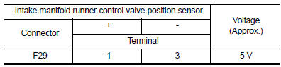
Is the inspection result normal? YES >> GO TO 6.
NO >> GO TO 2.
2.CHECK INTAKE MANIFOLD RUNNER CONTROL VALVE POSITION SENSOR POWER SUPPLY CIRCUIT
Check the voltage between intake valve manifold runner control valve position sensor harness connector and ground.
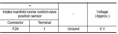
Is the inspection result normal? YES >> GO TO 4.
NO >> GO TO 3.
3.CHECK SENSOR POWER SUPPLY 2 CIRCUIT
Check sensor power supply 2 circuit. Refer to EC-444, "Diagnosis Procedure".
Is inspection result normal? YES >> Perform the trouble diagnosis for power supply circuit.
NO >> Repair or replace error-detected parts.
4.CHECK ECM GROUND CIRCUIT
- Turn ignition switch OFF.
- Disconnect ECM harness connector.
- Check the continuity between ECM harness connector and ground.
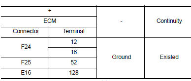
- Also check harness for short to power.
Is the inspection result normal? YES >> Check intermittent incident. Refer to GI-39, "Intermittent Incident".
NO >> Repair or replace error-detected parts.
5.CHECK INTAKE MANIFOLD RUNNER CONTROL VALVE POSITION SENSOR GROUND CIRCUIT
- Turn ignition switch OFF.
- Disconnect ECM harness connector.
- Check the continuity between intake manifold runner control valve position sensor harness connector and ECM harness connector.
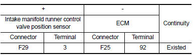
- Also check harness for short to power.
Is the inspection result normal? YES >> GO TO 6.
NO >> Repair or replace error-detected parts.
6.CHECK INTAKE MANIFOLD RUNNER CONTROL VALVE POSITION SENSOR INPUT SIGNAL CIRCUIT
- Check the continuity between intake manifold runner control valve position sensor harness connector and ECM harness connector.
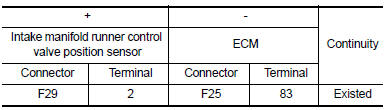
- Also check harness for short to ground and to power.
Is the inspection result normal? YES >> GO TO 7.
NO >> Repair or replace error-detected parts.
7.CHECK INTERMITTENT INCIDENT
Perform GI-39, "Intermittent Incident".
Is the inspection result normal? YES >> Replace intake manifold assembly. Refer to EM-27, "Exploded View".
NO >> Repair or replace error-detected parts.
 P2004 Intake manifold runner control valve
DTC Logic
DTC DETECTION LOGIC
DTC No.
CONSULT screen terms
(Trouble diagnosis content)
DTC detecting condition
Possible cause
P2004
TUMBLE CONT/V
(Intake manifold r ...
 P2096, P2097 A/F Sensor 1
DTC Logic
DTC DETECTION LOGIC
DTC No.
CONSULT screen terms
(Trouble diagnosis content)
DTC detecting condition
Possible Cause
P2096
POST CAT FUEL TRIM SYS B1
(Post ...
Other materials:
On board diagnostic (OBD) system
Diagnosis Description
This system is an on board diagnostic system that records exhaust
emission-related diagnostic information
and detects a sensors/actuator-related malfunction. A malfunction is indicated
by the malfunction indicator
lamp (MIL) and stored in ECU memory as a DTC. The diagnos ...
SRS Air bag warning lamp does not turn ON
Diagnosis Procedure
1.CHECK COMBINATION METER POWER SUPPLY AND GROUND CIRCUIT
Check combination meter unit power supply and ground circuit. Refer to
MWI-52, "COMBINATION METER :
Diagnosis Procedure".
Is the inspection result normal?
YES >> GO TO 2.
NO >> Repair or r ...
Excessive abs function operation
frequency
Diagnosis Procedure
1.CHECK START
Check front and rear brake force distribution using a brake
tester.
Is the inspection result normal?
YES >> GO TO 2
NO >> Check brake system.
2.CHECK FRONT AND REAR AXLE
Make sure that there is no excessive play in the front and rear
axles. ...
