Nissan Sentra Service Manual: P0712 Transmission fluid temperature sensor A
DTC Logic
DTC DETECTION LOGIC
| DTC | CONSULT screen terms (Trouble diagnosis content) | DTC detection condition | Possible causes |
| P0712 | FLUID TEMP SENSOR A (Transmission Fluid Temperature Sensor A Circuit Low) | The CVT fluid temperature identified by the
TCM is 180В°C (356В°F) or more continuously
for 5 seconds or more under the following diagnosis
conditions: Diagnosis conditions
|
|
DTC CONFIRMATION PROCEDURE
1.PREPARATION BEFORE WORK
If another “DTC CONFIRMATION PROCEDURE” occurs just before, turn ignition switch OFF and wait for at least 10 seconds, then perform the next test.
>> GO TO 2.
2.PERFORM DTC CONFIRMATION PROCEDURE
- Start the engine and wait for 10 seconds or more.
- Check the first trip DTC.
Is “P0712” detected? YES >> Go to TM-174, "Diagnosis Procedure".
NO >> INSPECTION END
Diagnosis Procedure
1.CHECK CIRCUIT BETWEEN TCM AND CVT UNIT
- Turn ignition switch OFF.
- Disconnect TCM connector and CVT unit connector.
- Check continuity between TCM harness connector terminal and ground.
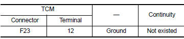
Is the inspection result normal? YES >> GO TO 2.
NO >> Repair or replace malfunctioning part.
2.CHECK CVT FLUID TEMPERATURE SENSOR
Check CVT fluid temperature sensor. Refer to TM-174, "Component Inspection".
Is the inspection result normal? YES >> Check intermittent incident. Refer to GI-39, "Intermittent Incident".
NO >> Repair or replace malfunctioning parts.
Component Inspection
1.CHECK CVT FLUID TEMPERATURE SENSOR
Check resistance between CVT unit connector terminals.
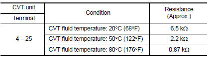
Is the inspection result normal? YES >> INSPECTION END
NO >> There is a malfunction of CVT fluid temperature sensor. Replace transaxle assembly. Refer to TM-283, "Removal and Installation".
 P0711 Transmission fluid temperature sensor A
DTC Logic
DTC DETECTION LOGIC
DTC
CONSULT screen terms
(Trouble diagnosis content)
DTC detection condition
Possible causes
P0711
FLUID TEMP SENSOR A
(Transmission F ...
 P0713 Transmission fluid temperature sensor A
DTC Logic
DTC DETECTION LOGIC
DTC
CONSULT screen terms
(Trouble diagnosis content)
DTC detection condition
Possible causes
P0713
FLUID TEMP SENSOR A
(Transmission ...
Other materials:
Exterior rear
Trunk lid
High mount stop light
Replacing bulbs
Rear window defroster switch
Child safety rear door lock
Fuel-filler door , Fuel-filler cap,fuel recommendation
Rearview camera (if so equipped)
Exterior trunk lid release, Interior trunk lid release (if so equipped)
See the pag ...
Wiring diagram
Power door lock system
Wiring diagram
Intelligent key system
Wiring diagram
Trunk lid opener
Wiring diagram
...
Drinking alcohol/drugs and driving
WARNINGNever drive under the influence of alcohol
or drugs. Alcohol in the bloodstream reduces
coordination, delays reaction time
and impairs judgement. Driving after
drinking alcohol increases the likelihood
of being involved in an accident injuring
yourself and others. Add ...
