Nissan Sentra Service Manual: P0720 Output speed sensor
DTC Logic
DTC DETECTION LOGIC
| DTC | CONSULT screen terms (Trouble diagnosis content) | DTC detection condition | Possible causes |
| P0720 | OUTPUT SPEED SENSOR (Output Speed Sensor Circuit) | The output speed sensor value is less than
150 rpm continuously for 5 seconds or more
under the following diagnosis conditions: Diagnosis conditions
|
|
| The output speed sensor value is 90 rpm or
less continuously for 500 msec or more under
the following diagnosis conditions: Diagnosis conditions
|
DTC CONFIRMATION PROCEDURE
CAUTION:
Be careful of the driving speed.
1.PREPARATION BEFORE WORK
If another –≤–Ç—öDTC CONFIRMATION PROCEDURE–≤–Ç—ú occurs just before, turn ignition switch OFF and wait for at least 10 seconds, then perform the next test.
>> GO TO 2.
2.CHECK DTC DETECTION
- Start the engine.
- Drive the vehicle.
- Maintain the following conditions for 10 seconds or more.
Selector lever : –≤–Ç—öD–≤–Ç—ú position
Vehicle speed : 55 km/h (34 MPH) or more
- Stop the vehicle.
- Check the first trip DTC.
Is –≤–Ç—öP0720–≤–Ç—ú detected? YES >> Go to TM-181, "Diagnosis Procedure".
NO >> INSPECTION END
Diagnosis Procedure
1.CHECK OUTPUT SPEED SENSOR POWER CIRCUIT
- Turn ignition switch OFF.
- Disconnect output speed sensor connector.
- Turn ignition switch ON.
- Check voltage between output speed sensor harness connector terminal and ground.
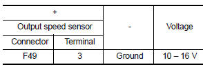
Is the check result normal? YES >> GO TO 2.
NO >> GO TO 6.
2.CHECK OUTPUT SPEED SENSOR GROUND CIRCUIT
Check the continuity between output speed sensor harness connector terminal and ground.
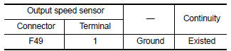
Is the check result normal? YES >> GO TO 3.
NO >> Repair or replace malfunctioning parts.
3.CHECK CIRCUIT BETWEEN OUTPUT SPEED SENSOR AND TCM (PART 1)
- Turn ignition switch OFF.
- Disconnect TCM connector
- Check continuity between output speed sensor harness connector terminal and TCM harness connector terminal.
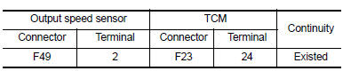
Is the check result normal? YES >> GO TO 4.
NO >> Repair or replace malfunctioning parts.
4.CHECK CIRCUIT BETWEEN OUTPUT SPEED SENSOR AND TCM (PART 2)
Check continuity between output speed sensor harness connector terminal and ground.
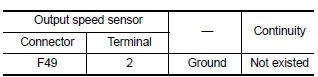
Is the check result normal? YES >> GO TO 5.
NO >> Repair or replace malfunctioning parts.
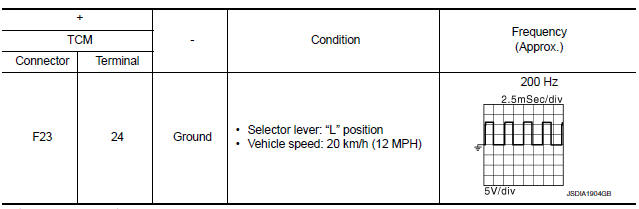
5.Check tcm input signals
- Connect all of disconnected connectors.
- Lift the vehicle.
- Start the engine.
- Check frequency of output speed sensor.
Is the check result normal? YES >> Check intermittent incident. Refer to GI-39, "Intermittent Incident".
NO >> Replace output speed sensor. Refer to TM-270, "Exploded View".
6.DETECT MALFUNCTIONING ITEMS
Check the following items:
- Harness open circuit or short circuit between ignition switch and IPDM E/R. Refer to PG-20, "Wiring Diagram — Ignition Power Supply —".
- Harness open circuit or short circuit between IPDM E/R and output speed sensor.
- 10A fuse (No.45, IPDM E/R). Refer to PG-49, "IPDM E/R Terminal Arrangement".
- IPDM E/R
Is the check result normal? YES >> Check intermittent incident. Refer to GI-39, "Intermittent Incident".
NO >> Repair or replace malfunctioning parts.
 P0715 Input speed sensor A
DTC Logic
DTC DETECTION LOGIC
DTC
CONSULT screen terms
(Trouble diagnosis content)
DTC detection condition
Possible causes
P0715
INPUT SPEED SENSOR A
...
 P0740 Torque converter
DTC Logic
DTC DETECTION LOGIC
DTC
CONSULT screen terms
(Trouble diagnosis content)
DTC detection condition
Possible causes
P0740
TORQUE CONVERTER
(Torque Converter ...
Other materials:
Operating tips
When the engine coolant temperature and
outside air temperature are low, the air flow
from the foot outlets may not operate for a
maximum of 150 seconds. However, this is
not a malfunction. After the coolant temperature
warms up, air flow from the foot outlets
will operate normally.
...
Headlamp (hi) circuit
Description
The IPDM E/R (intelligent power distribution module engine room) controls the
headlamp high relay based on
inputs from the BCM over the CAN communication lines. When the headlamp high
relay is energized, power
flows through fuses 41 and 42, located in the IPDM E/R. Power then flo ...
Front drive shaft boot
Exploded View
(LH)
Circular clip
Dust shield
Slide joint housing
Snap ring
Spider assembly
Boot band
Boot
Shaft
Damper band
Dynamic damper
Circular clip
Joint sub-assembly
Wheel side
(RH) 6M/T
Joint sub-assembly
Circular clip
Boot band
Boot
Shaft
Dam ...
