Nissan Sentra Service Manual: Meter buzzer circuit
Description
- The buzzer for warning chime system is installed in the combination meter.
- The combination meter sounds the alarm buzzer based on the signals transmitted from various units.
Component function check
1.Check operation of meter buzzer
- Select BUZZER of BCM on CONSULT.
- Perform LIGHT WARN ALM of Active Test.
Does meter buzzer activate? YES >> Inspection End.
NO >> Refer to WCS-28, "Diagnosis Procedure".
Diagnosis procedure
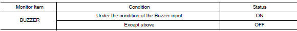
1.Check combination meter input signal
Select the Data Monitor for the METER/M&A and check the BUZZER monitor value.
Is the inspection result normal? Yes >> replace combination meter. Refer to mwi-77, "removal and installation".
No >> replace bcm. Refer to bcs-73, "removal and installation" (with intelligent key) or bcs-126, "removal and installation" (without intelligent key).
 Power supply and ground circuit
Combination meter
Combination meter : diagnosis procedure
Regarding Wiring Diagram information, refer to MWI-28, "Wiring Diagram".
1.Check fuses
Check that the following fuses are not bl ...
 Seat belt buckle switch signal circuit
Description
Transmits a seat belt buckle switch lh (driver seat) signal to the
combination meter
Component function check
1. Check combination meter input signal
Select data monitor for meter/ ...
Other materials:
P0462, P0463 Fuel level sensor
DTC Logic
DTC DETECTION LOGIC
NOTE:
If DTC P0462 or P0463 is displayed with DTC UXXXX, first perform the
trouble diagnosis for DTC
UXXXX.
If DTC P0462 or P0463 is displayed with DTC P0607, first perform the
trouble diagnosis for DTC
P0607. Refer to EC-350, "DTC Logic".
...
Connector symbols
Most of connector symbols in wiring diagrams are shown from the terminal
side.
Connector symbols shown from the terminal side are enclosed by
a single line and followed by the direction mark.
Connector symbols shown from the harness side are enclosed by
a double line and followed by the ...
P0606 ECM
DTC Logic
DTC DETECTION LOGIC
DTC No.
CONSULT screen terms
(Trouble diagnosis content)
DTC detecting condition
Possible cause
P0606
CONTROL MODULE
(Control module processor)
Malfunction in ECM processor.
ECM
DTC CONFIRMATION PROCEDURE
1.PRECONDITIONIN ...
