Nissan Sentra Service Manual: Connector symbols
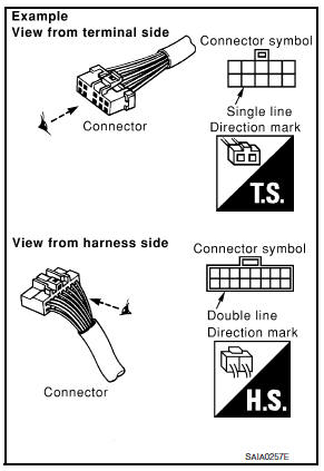
Most of connector symbols in wiring diagrams are shown from the terminal side.
- Connector symbols shown from the terminal side are enclosed by a single line and followed by the direction mark.
- Connector symbols shown from the harness side are enclosed by a double line and followed by the direction mark.
- Certain systems and components, especially those related to
OBD, may use a new style slide-locking type harness connector.
For description and how to disconnect, refer to PG section, “Description”, “HARNESS CONNECTOR”.
- Male and female terminals
Connector guides for male terminals are shown in black and female terminals in white in wiring diagrams.

 Sample/wiring diagram -example-
For detail, refer to following GI-11, "Description".
...
Other materials:
Precaution for supplemental restraint system (srs) "air bag" and "seat belt
pre-tensioner"
The supplemental restraint system such as “air bag” and “seat belt pre-tensioner”,
used along
with a front seat belt, helps to reduce the risk or severity of injury to the
driver and front passenger for certain
types of collision. Information necessary to service the system ...
Preparation
Special Service Tool
The actual shape of the tools may differ from those illustrated here.
Commercial Service Tool
Clip list
Descriptions for clips
Replace any clips which are damaged during removal or installation.
...
Variable voltage control system
CAUTION
Do not ground accessories directly to
the battery terminal. Doing so will bypass
the variable voltage control system
and the vehicle battery may not
charge completely.
Use electrical accessories with the engine
running to avoid discharging the
vehicle battery.
Your v ...
