Nissan Sentra Service Manual: Power supply and ground circuit
Combination meter
Combination meter : diagnosis procedure
Regarding Wiring Diagram information, refer to MWI-28, "Wiring Diagram".
1.Check fuses
Check that the following fuses are not blown.
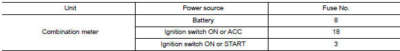
Is the fuse blown? YES >> Replace the blown fuse after repairing the affected circuit.
NO >> GO TO 2.
2.Power supply circuit check
Check voltage between combination meter harness connector M24 terminals 15, 27, 28 and ground.
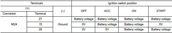
Is the inspection result normal? YES >> GO TO 3.
NO >> Repair or replace harness or connector.
3.Check ground circuit
Check continuity between combination meter harness connector m24 terminals 21, 22, 23 and ground.
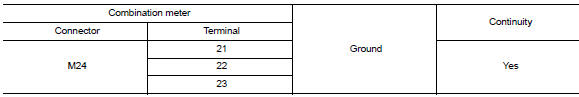
Is the inspection result normal? Yes >> inspection end.
No >> repair or replace harness or connector.
Bcm (body control system) (with intelligent key system)
Bcm (body control system) (with intelligent key system) : diagnosis procedure
Regarding wiring diagram information, refer to bcs-51, "wiring diagram".
1.Check fuses and fusible link
Check that the following fuses and fusible link are not blown.
Is the fuse blown? Yes >> replace the blown fuse or fusible link after repairing the affected circuit.
No >> go to 2.
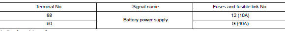
2.Check power supply circuit
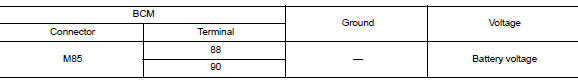
- Disconnect bcm connector m85.
- Check voltage between bcm connector m85 and ground.
Is the inspection result normal? Yes >> go to 3.
No >> repair harness or connector.
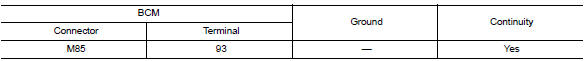
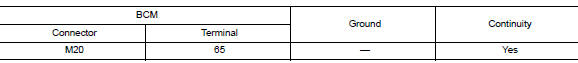
3.Check ground circuit
Check continuity between bcm connector m85 and ground.
Is the inspection result normal? Yes >> inspection end.
No >> repair harness or connector.
Bcm (body control system) (without intelligent key system)
Bcm (body control system) (without intelligent key system) : diagnosis procedure
Regarding wiring diagram information, refer to bcs-111, "wiring diagram".
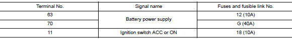
1.Check fuses and fusible link
Check that the following fuses and fusible link are not blown.
Is the fuse blown?
Yes >> replace the blown fuse or fusible link after repairing the affected circuit.
No >> go to 2.
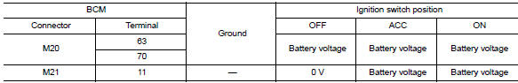
2.Check power supply circuit
- Turn ignition switch off.
- Disconnect bcm connectors.
- Check voltage between bcm connector and ground.
Is the inspection result normal? YES >> GO TO 3.
NO >> Repair harness or connector.
3.Check ground circuit
Check continuity between bcm connector and ground.
Is the inspection result normal? Yes >> inspection end.
No >> repair harness or connector.

 Meter buzzer circuit
Description
The buzzer for warning chime system is installed in the combination
meter.
The combination meter sounds the alarm buzzer based on the signals
transmitted from various units.
...
Other materials:
Ecu diagnosis information
BCM
Reference value
Note:
The signal tech ii tool (j-50190) can be used to perform the following
functions. Refer to the signal tech ii
user guide for additional information.
Activate and display tpms transmitter ids
Display tire pressure reported by the tpms transmitter
Read TPMS DTCs ...
Wiring diagram
Intelligent key system/engine start function
Wiring diagram
Nissan vehicle immobilizer systemnats
Wiring Diagram
Vehicle security system
Wiring diagram
...
Daytime light relay circuit
Description
The bcm sends a daytime light request to the ipdm e/r via the can
communication lines. The power flows
through fuse 29 located in fuse block j/b to the daytime light relay coil. When
the ipdm e/r operates the daytime
light relay, power is sent to the daytime lamps.
Diagnosis proc ...
