Nissan Sentra Service Manual: Ecu diagnosis information
BCM
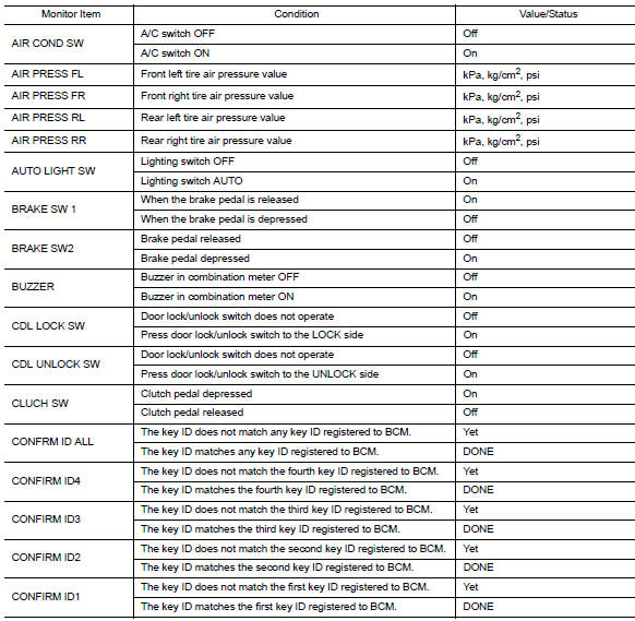
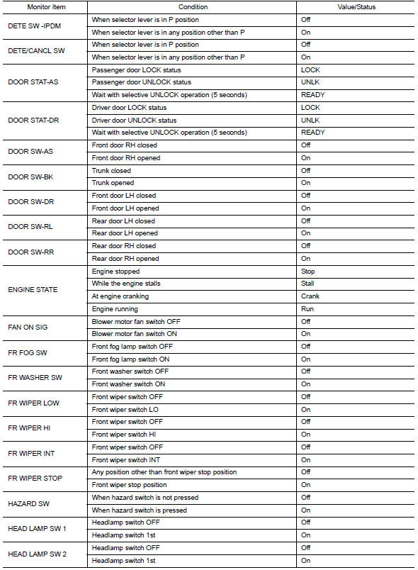
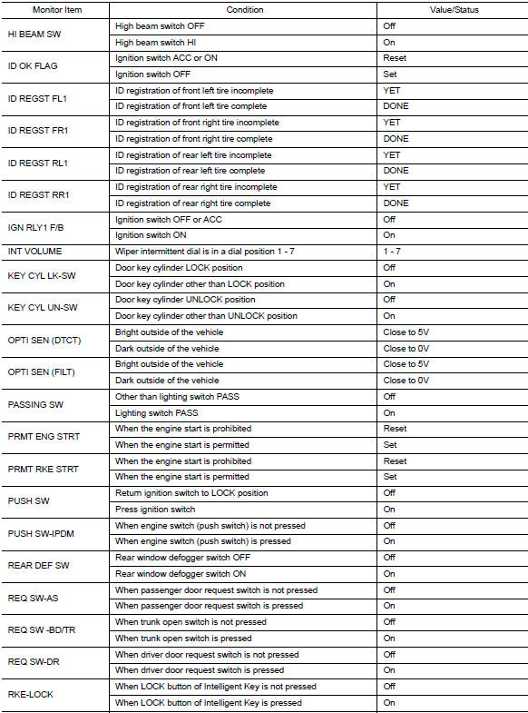
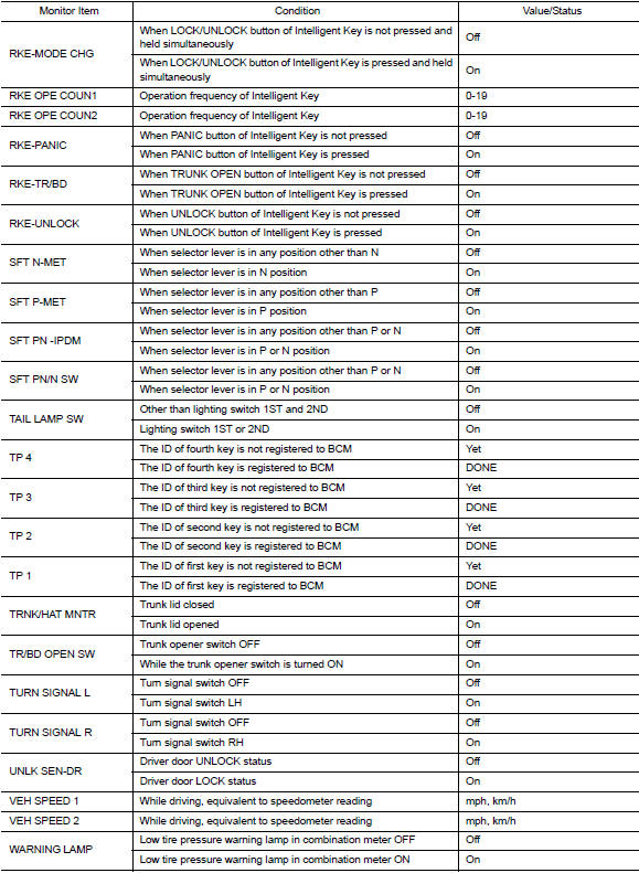
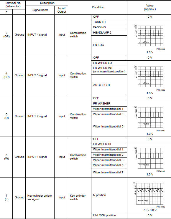
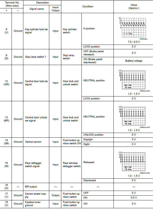
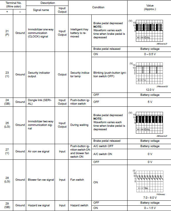
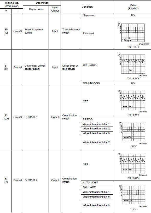
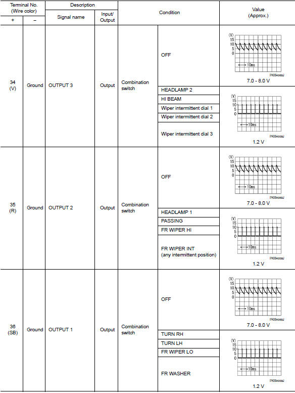
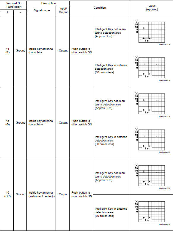
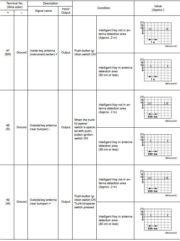
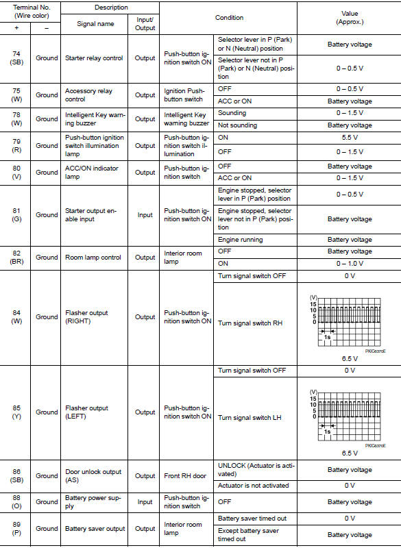
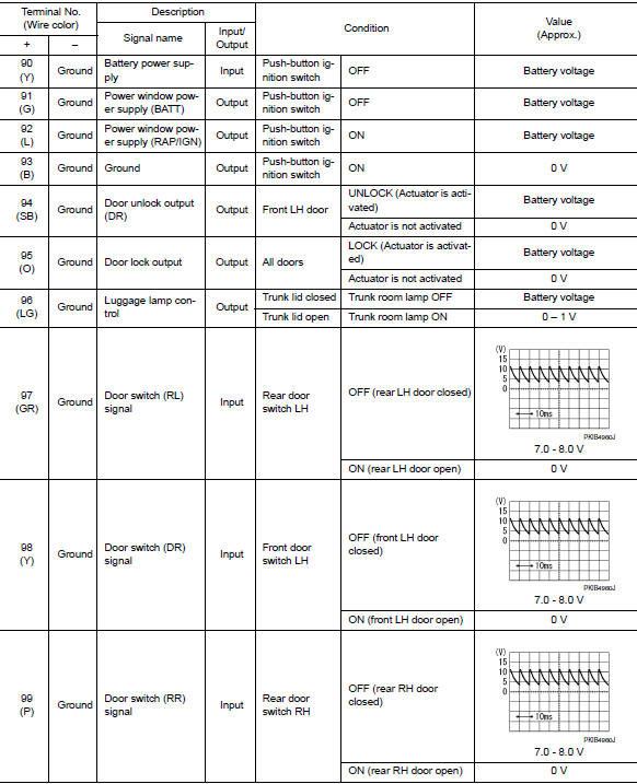
Reference value
Note:
The signal tech ii tool (j-50190) can be used to perform the following functions. Refer to the signal tech ii user guide for additional information.
- Activate and display tpms transmitter ids
- Display tire pressure reported by the tpms transmitter
- Read TPMS DTCs
- Register TPMS transmitter IDs
- Check intelligent key relative signal strength
- Confirm vehicle intelligent key antenna signal strength
Values on the diagnosis tool
Terminal layout

Physical values

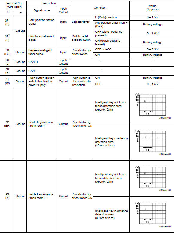

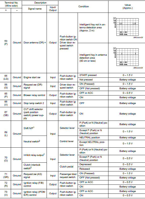

1: With cvt
2: With m/t
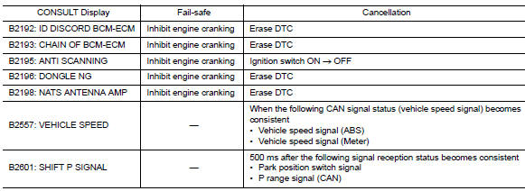
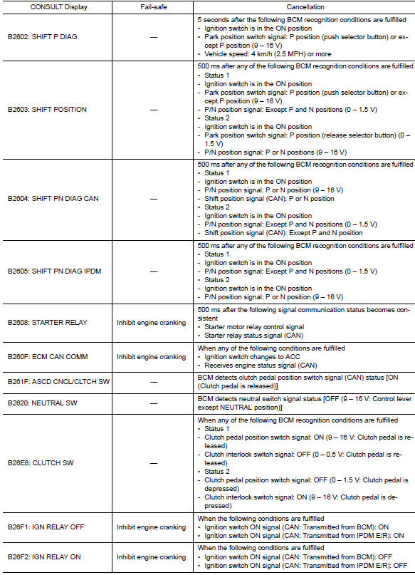
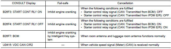
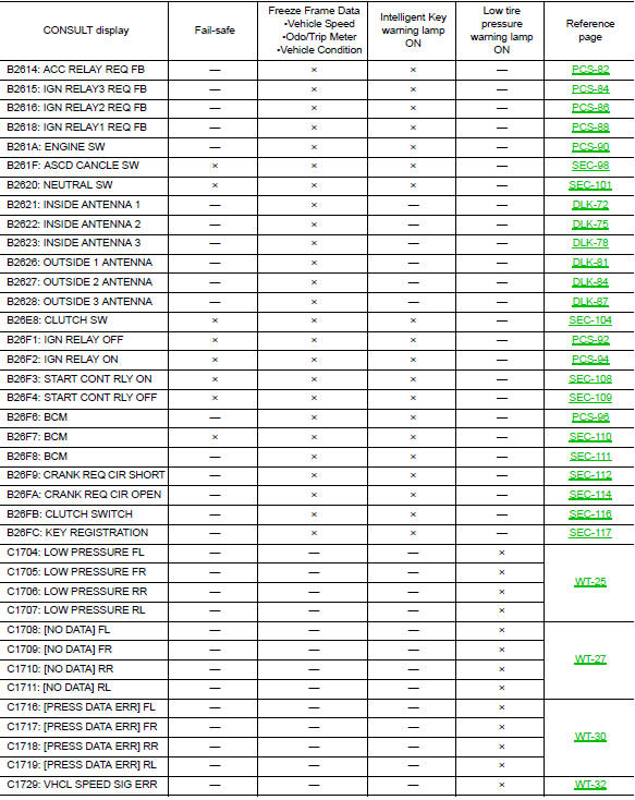
Fail-safe
Bcm performs fail-safe control when the following dtcs are detected.
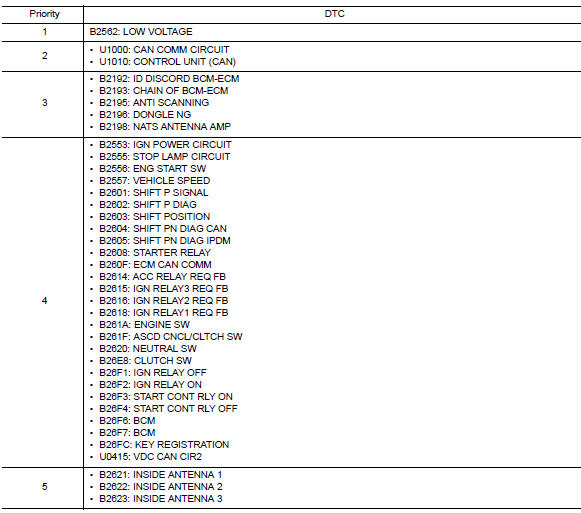
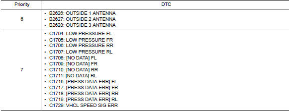
Dtc inspection priority chart
If more than one DTC is displayed at the same time, perform inspections based on the following priority chart.
Dtc index
Note:
The details of time display are as follows.
- Crnt: a malfunction is detected now.
- Past: a malfunction was detected in the past.
IGN counter is displayed on Freeze Frame Data.

 Diagnosis system (bcm)
Common item
COMMON ITEM : CONSULT Function (BCM - COMMON ITEM)
Application item
Consult performs the following functions via can communication with bcm.
Direct diagnostic mode
Descriptio ...
 Wiring diagram
BCM
Wiring diagram
...
Other materials:
Brake booster
Exploded View
Master cylinder assembly
Brake booster
Lock nut
Clevis
Gasket
Spacer
Removal and installation
REMOVAL
Remove cowl top and cowl top extension. Refer to EXT-26, "Removal and
Installation".
Remove air duct and air cleaner case. Refer to EM-25, &qu ...
Exhaust manifold
Exploded View
CALIFORNIA
Air fuel ratio sensor
Exhaust manifold heat shield (upper)
Exhaust manifold and three way catalyst
Exhaust manifold heat shield (rear)
Exhaust manifold heat shield (front)
Exhaust manifold gasket
Cylinder head
EXCEPT CALIFORNIA
Air fuel ratio ...
Wiper and washer fuse
Description
Diagnosis procedure
1. Check fuses
Check that the following fuses are not blown.
Is the fuse blown?
Yes >> replace the blown fuse after repairing the affected circuit.
No >> inspection end. ...
