Nissan Sentra Service Manual: Drive belt
Exploded View
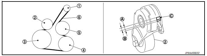
- Alternator
- Drive belt auto-tensioner
- Crankshaft pulley
- A/C compressor
- Water pump
- Drive belt
- Possible use range
- New drive belt range
- Indicator
Removal and Installation
REMOVAL
- Remove the front fender protector (RH) front side bolts and clips. Refer to EXT-27, "FENDER PROTECTOR : Exploded View".
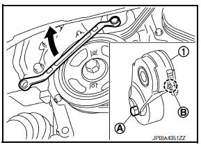
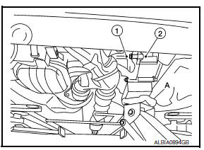
- Hold the hexagonal part (A) of drive belt auto-tensioner (1) with a wrench securely. Then move the wrench handle in the direction of arrow (loosening direction of drive belt auto-tensioner).
WARNING:
Avoid placing hand in a location where pinching may occur if the holding tool accidentally comes off.
- Insert a rod approximately 6 mm (0.24 in) in diameter into the hole (B) of the retaining boss to lock drive belt auto-tensioner.
- Keep drive belt auto-tensioner pulley arm locked after drive belt is removed.
- Remove drive belt.
INSTALLATION
- Install drive belt.
CAUTION:
- Confirm drive belt is completely set to pulleys.
- Check for engine oil and engine coolant, be sure they are not adhered to drive belt and each pulley groove.
- Release drive belt auto-tensioner, and apply tension to drive belt.
WARNING:
Avoid placing hand in a location where pinching may occur if the holding tool accidentally comes off.
- Turn crankshaft pulley clockwise several times to equalize tension between each pulley.
- Confirm tension of drive belt at indicator (notch on fixed side) is within the possible use range. Refer to EM-15, "Exploded View".
- Install the front fender protector (RH) front side bolts and clips. Refer to EXT-27, "FENDER PROTECTOR : Exploded View".
Inspection
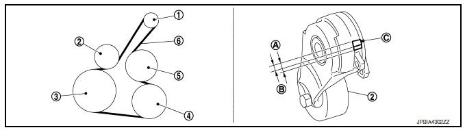
- Alternator
- Drive belt auto-tensioner
- Crankshaft pulley
- A/C compressor
- Water pump
- Drive belt
- Possible use range
- New drive belt range
- Indicator
WARNING:
Perform this step when engine is stopped.
- Check that the indicator of drive belt auto-tensioner is within the possible use range.
NOTE:
- Check the drive belt auto-tensioner indication when the engine is cold.
- When new drive belt is installed, the indicator should be within the new drive belt range.
- Visually check entire drive belt for wear, damage or cracks.
- If the indicator is out of the possible use range or belt is damaged, replace drive belt.
Adjustment
Belt tension is not necessary, as it is automatically adjusted by drive belt auto-tensioner.
Exploded View
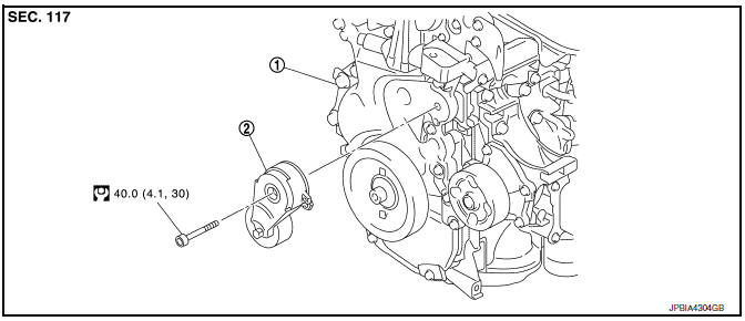
- Front cover
- Drive belt auto-tensioner
Removal and Installation
Removal
- Remove engine under cover. Refer to EXT-31, "ENGINE UNDER COVER : Exploded View".
- Remove engine room cover. Refer to EM-24, "Exploded View".
- Partially remove fender protector side cover (RH). Refer to EXT-27, "FENDER PROTECTOR : Exploded View".
- Remove drive belt. Refer to EM-15, "Exploded View".
- Support engine (1) and transaxle (2) using suitable jack (A).
CAUTION:
- Position a suitable jack under the engine and transaxle assembly as shown.
- Do not damage the front exhaust tube or transaxle oil pan with the jack.
- Remove upper torque rod and engine mounting insulator (RH). Refer to EM-82, "M/T : Exploded View" (for M/T) or EM-86, "CVT : Exploded View" (for CVT).
- Remove drive belt auto-tensioner.
Installation
Installation is in the reverse order of removal
CAUTION:
When installing drive belt auto-tensioner, be careful not to interfere with water pump pulley.
 Spark plug
Exploded View
Ignition coil
Spark plug
Rocker cover
Removal and Installation
REMOVAL
Remove engine cover. Refer to EM-24, "Exploded View".
Remove ignition coil. Refer t ...
 Air cleaner filter
Exploded View
Mass air flow sensor
Mass air flow gasket
Clamp
Air duct (suction side)
Resonator
Clamp
PCV hose
Clamp
Clamp
Air cleaner cover
Mounting rubber
Air cleaner f ...
Other materials:
iPod®* player operation with Navigation System (if so equipped)
Connecting iPod®
WARNINGDo not connect, disconnect or operate the
USB device while driving. Doing so can be
a distraction. If distracted you could lose
control of your vehicle and cause an accident
or serious injury.
CAUTION
Do not force the USB device into the
U ...
Removal and installation
ACCELERATOR CONTROL SYSTEM
Exploded View
Accelerator pedal assembly
Brake pedal bracket
Locating hook
Locating pin
Removal and Installation
REMOVAL
Remove instrument lower panel LH. Refer to IP-21, "Removal and
Installation".
Disconnect the harness connector ...
Regulatory Information
FCC Regulatory information
CAUTION: To maintain compliance with
FCC’s RF exposure guidelines, use only the
supplied antenna. Unauthorized antenna,
modification, or attachments could damage
the transmitter and may violate FCC regulations.
Operation is subject to the following two cond ...
