Nissan Sentra Service Manual: Spark plug
Exploded View
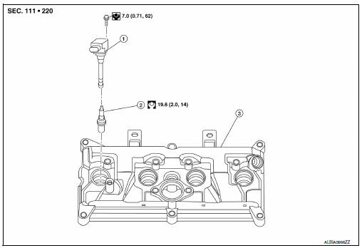
- Ignition coil
- Spark plug
- Rocker cover
Removal and Installation
REMOVAL
- Remove engine cover. Refer to EM-24, "Exploded View".
- Remove ignition coil. Refer to EM-46, "Exploded View".
- Remove spark plug using suitable tool.
(a) : 14 mm (0.55 in)
CAUTION:
Do not drop or shock spark plug.
INSTALLATION
Installation is in the reverse order of removal.
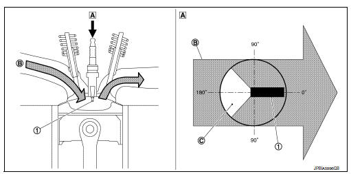
*: Always check with the Parts Department for the latest parts information.
CAUTION:
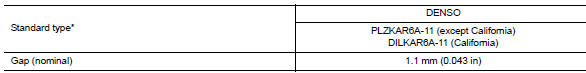
Always tighten the spark plug to specified torque to align the orientation of electrodes. The ground electrode of a genuine spark plug is positioned in the area of maximum ignitability by tightening to the specified torque. When replacing spark plugs, use genuine spark plugs of which the ground electrode is adjusted.
NOTE:
The ground electrode of the spark plug is positioned in the area of maximum ignitability to improve combustion efficiency in the cylinder, reduce CO2 (carbon dioxide) emission and improve fuel economy.
- Ground electrode of spark plug
- Top view
- Air-fuel mixture flow
- Poor ignitability region
Inspection
INSPECTION AFTER REMOVAL
Use the standard type spark plug for normal condition.
Spark plug (Standard type) : Refer to EM-118, "Spark Plug".
CAUTION:
- Do not drop or shock spark plug.
- Do not use a wire brush for cleaning.
- If plug tip is covered with carbon, spark plug cleaner may be used.
Cleaner air pressure : Less than 588 kPa (6 kg/cm2, 85 psi)
Cleaning time : Less than 20 seconds
- Spark plug gap adjustment is not required between replacement intervals.
- Measure spark plug gap. when it exceeds the limit, replace
spark plug even if it is with in the specified replacement mileage.
Refer to EM-118, "Spark Plug".

 Drive belt
Exploded View
Alternator
Drive belt auto-tensioner
Crankshaft pulley
A/C compressor
Water pump
Drive belt
Possible use range
New drive belt range
Indicator
Removal and ...
Other materials:
Strg branch line circuit
Diagnosis procedure
1.Check connector
Turn the ignition switch OFF.
Disconnect the battery cable from the negative terminal.
Check the terminals and connectors of the steering angle sensor for
damage, bend and loose connection
(unit side and connector side).
Is the inspection result ...
Removal and installation
Combination meter
Exploded view
Combination meter
Front cover
Removal and installation
Removal
Remove cluster lid a. Refer to ip-19, "removal and installation".
Remove the screws from the combination meter.
Remove the combination meter.
Disconnect the comb ...
Vehicle loading information
WARNING
It is extremely dangerous to ride
in a cargo area inside a vehicle. In
a collision, people riding in these
areas are more likely to be seriously
injured or killed.
Do not allow people to ride in any
area of your vehicle that is not
equipped with seats a ...
