Nissan Sentra Service Manual: Removal and installation
ACCELERATOR CONTROL SYSTEM
Exploded View
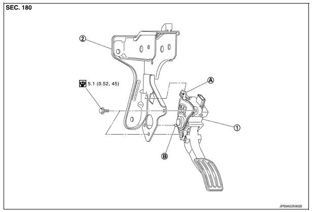
- Accelerator pedal assembly
- Brake pedal bracket
- Locating hook
- Locating pin
Removal and Installation
REMOVAL
- Remove instrument lower panel LH. Refer to IP-21, "Removal and Installation".
- Disconnect the harness connector From the accelerator pedal assembly.
- Loosen bolts and remove accelerator pedal assembly.
CAUTION:
- Do not disassemble accelerator pedal assembly.
- Do not remove accelerator pedal position sensor from accelerator pedal assembly.
- Do not drop or impact the accelerator pedal assembly.
- Do not expose the accelerator pedal assembly to water.
INSTALLATION
Installation is in the reverse order of removal.
- Insert the locating hook and pin into the brake pedal bracket.
CAUTION:
Do not squeeze the locating hook into the brake pedal bracket when inserting the locating pin into the hole on the brake pedal bracket side.
Inspection
INSPECTION AFTER INSTALLATION
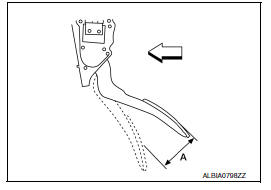
- Check that the accelerator pedal moves smoothly within the specified range.
Accelerator pedal stroke (A) : Refer to ACC-5, "Accelerator Control"
- For the electrical inspection of accelerator pedal position sensor. Refer to EC-138, "Work Procedure".
CAUTION:
- Whenever the harness connector of accelerator pedal position sensor is disconnected, perform “ACCELERATOR PEDAL RELEASED POSITION LEARNING”. Refer to EC-138, "Work Procedure".
- The accelerator pedal should return smoothly to the fully raised position.
 Precaution
Precaution for Supplemental Restraint System (SRS) "AIR BAG" and "SEAT
BELT PRE-TENSIONER"
The Supplemental Restraint System such as “AIR BAG” and “SEAT BELT PRE- ...
 Service data and specifications (SDS)
Accelerator Control
...
Other materials:
P0524 Engine oil pressure
DTC Logic
DTC DETECTION LOGIC
DTC No.
CONSULT screen terms
(Trouble diagnosis content)
DTC detecting condition
Possible cause
P0524
ENGINE OIL PRESSURE
(Engine oil pressure too low)
An EOP sensor signal voltage applied to
ECM remains lower than the specified ...
Basic inspection
Diagnosis and repair work flow
Work flow
Detailed flow
1.Obtain information about symptom
Interview the customer to obtain as much information as possible about the
conditions and environment under
which the malfunction occurs.
>> GO TO 2.
2.Check symptom
Check the symptom based ...
Read first—then drive safely
FOREWORD
Welcome to the growing family of new NISSAN
owners. This vehicle is delivered to you with
confidence. It was produced using the latest
techniques and strict quality control.
This manual was prepared to help you understand
the operation and maintenance of your
vehicle so that you ma ...
