Nissan Sentra Service Manual: Door switch
Component Function Check
1.Check function
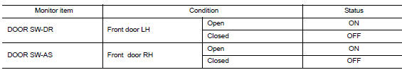
- Select DOOR LOCK of BCM using CONSULT
- Select door sw-dr, door sw-as in data monitor mode
- Check that the function operates normally according to the following conditions.
Is the inspection result normal? YES >> Door switch is OK.
NO >> Refer to RF-26, "Diagnosis Procedure".
Diagnosis Procedure
Regarding wiring diagram information, refer to dlk-49, "wiring diagram".
1.Check door switch input signal
- Turn ignition switch off.
- Disconnect malfunctioning door switch connector.
- Check signal between malfunctioning door switch harness connector and ground using oscilloscope.
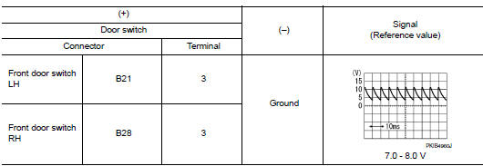
Is the inspection result normal? Yes >> go to 3.
No >> go to 2.
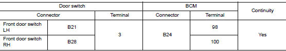
2.Check door switch circuit
- Disconnect BCM connector.
- Check continuity between door switch harness connector and bcm harness connector.
- Check continuity between door switch harness connector and ground.
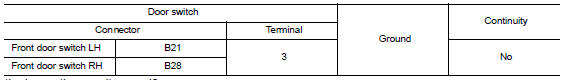
Is the inspection result normal? Yes >> replace bcm. Refer to bcs-73, "removal and installation".
No >> repair or replace harness.
3.Check door switch
Refer to rf-27, "component inspection".
Is the inspection result normal? Yes >> go to 4.
No >> replace malfunctioning door switch.
4.Check intermittent incident
Refer to gi-39, "intermittent incident".
>> Inspection end.
Component Inspection
1.Check door switch
- Turn ignition switch off.
- Disconnect malfunctioning door switch connector.
- Check continuity between door switch terminals.
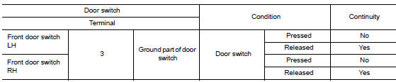
Is the inspection result normal? Yes >> inspection end.
No >> replace malfunction door switch.
 Moonroof switch
Description
Transmits switch operation signal to moonroof motor assembly.
Diagnosis Procedure
Regarding Wiring Diagram information, refer to RF-13, "Wiring Diagram".
1.Check moonroof sw ...

Other materials:
P0340 CMP Sensor (PHASE)
DTC Logic
DTC DETECTION LOGIC
DTC No.
CONSULT screen terms
(Trouble diagnosis content)
DTC detecting condition
Possible cause
P0340
CMP SEN/CIRC-B1
(Camshaft position sensor
“A” circuit bank 1)
The cylinder No. signal is not sent to ECM fo ...
Air conditioner operation (if so equipped)
Start the engine, turn the fan control dial to the
desired position, and press the
button to
activate the air conditioner. When the air conditioner
is on, cooling and dehumidifying functions
are added to the heater operation.
The air conditioner cooling function operates
only whe ...
Charging system
System Diagram
System Description
The generator provides DC voltage to operate the vehicle's electrical system
and to keep the battery charged.
The voltage output is controlled by the IC regulator.
Component Description
...
