Nissan Sentra Service Manual: Moonroof switch
Description
Transmits switch operation signal to moonroof motor assembly.
Diagnosis Procedure
Regarding Wiring Diagram information, refer to RF-13, "Wiring Diagram".
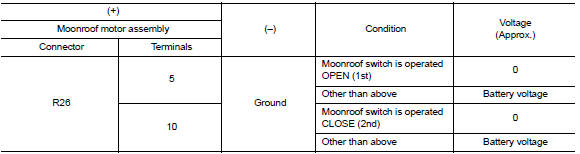
1.Check moonroof switch input signal
- Turn ignition switch on.
- Check voltage between moonroof motor assembly harness connector R26 and ground.
Is the inspection result normal? Yes >> inspection end.
No >> go to 2.
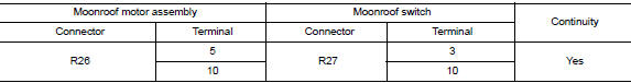
2.Check moonroof switch circuit
- Turn ignition switch OFF.
- Disconnect moonroof motor assembly connector and moonroof switch connector.
- Check continuity between moonroof motor assembly harness connector R26 and moonroof switch harness connector R27.
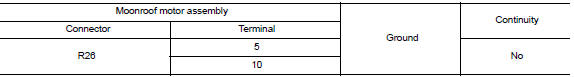
- Check continuity between moonroof motor assembly harness connector R26 and ground.
Is the inspection result normal? YES >> GO TO 3.
NO >> Repair or replace the harness or connectors.
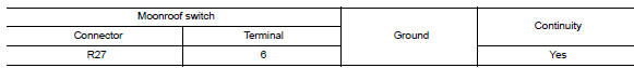
3.Check moonroof switch ground circuit
Check continuity between moonroof switch harness connector r27 and ground.
Is the inspection result normal? YES >> GO TO 4.
NO >> Repair or replace the harness or connectors.
4.Check moonroof switch
Check moonroof switch.
Refer to rf-25, "component inspection".
Is the inspection result normal? Yes >> go to 5.
No >> replace moonroof switch. Refer to rf-50, "removal and installation".
5.Check intermittent incident
Refer to gi-39, "intermittent incident".
>> Inspection end.
Component inspection
Moonroof switch
1. Check moonroof switch
- Turn ignition switch off.
- Disconnect moonroof switch.
- Check continuity between moonroof switch terminals.
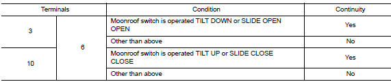
Is the inspection result normal? Yes >> moonroof switch is ok.
No >> replace moonroof switch. Refer to rf-50, "removal and installation".
 Power supply and ground circuit
Body control system
Body control system : diagnosis procedure
Regarding wiring diagram information, refer to bcs-51, "wiring diagram".
1.Check fuses and fusible link
Check that the follo ...
 Door switch
Component Function Check
1.Check function
Select DOOR LOCK of BCM using CONSULT
Select door sw-dr, door sw-as in data monitor mode
Check that the function operates normally according to the f ...
Other materials:
P0137 HO2S2
DTC Logic
DTC DETECTION LOGIC
The heated oxygen sensor 2 has a much longer switching time
between rich and lean than the air fuel ratio (A/F) sensor 1. The oxygen
storage capacity of the three way catalyst (manifold) causes the
longer switching time. To judge the malfunctions of heated oxygen
...
Component parts
Component parts location
BCM (view with instrument panel removed)
Key switch
(without Intelligent Key)
Push-button ignition switch
(with Intelligent Key)
IPDM E/R
Illumination control switch
Combination switch (lighting and
turn signal switch)
Front door lock LH (key cylin ...
Precaution for Supplemental Restraint System (SRS) "AIR BAG" and "SEAT BELT
PRE-TENSIONER"
The Supplemental Restraint System such as “AIR BAG” and “SEAT BELT PRE-TENSIONER”,
used along
with a front seat belt, helps to reduce the risk or severity of injury to the
driver and front passenger for certain
types of collision. Information necessary to service the system ...
