Nissan Sentra Service Manual: Brake pedal position switch
Component Function Check
1.CHECK BRAKE PEDAL POSITION SWITCH FUNCTION
 With CONSULT
- Turn ignition switch ON.
- Select đ▓đéĐÜENGINEđ▓đéĐť using CONSULT.
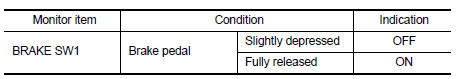
- Select đ▓đéĐÜBRAKE SW1đ▓đéĐť in đ▓đéĐÜDATA MONITORđ▓đéĐť mode.
- Check đ▓đéĐÜBRAKE SW1đ▓đéĐť indication under the following conditions.
 Without CONSULT
- Turn ignition switch ON.
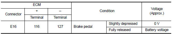
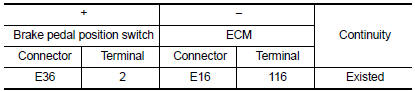
- Check the voltage between ECM harness connector terminals under the following conditions.
Is the inspection result normal? YES >> INSPECTION END
NO >> Proceed to EC-446, "Diagnosis Procedure".
Diagnosis Procedure
1.CHECK BRAKE PEDAL POSITION SWITCH POWER SUPPLY CIRCUIT
- Turn ignition switch OFF.
- Disconnect brake pedal position switch harness connector.
- Turn ignition switch ON.
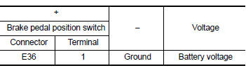
- Check the voltage between brake pedal position switch harness connector and ground.
Is the inspection result normal? YES >> GO TO 3.
NO >> GO TO 2.
2.CHECK STOP LAMP SWITCH POWER SUPPLY CIRCUIT
- Pull out #5 fuse.
- Check that the fuse is not fusing.
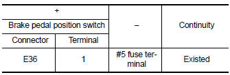
- Check the continuity between stop lamp switch harness connector and fuse terminal.
- Also check harness for short to ground and short to power.
Is the inspection result normal? YES >> Check power supply circuit for 12V battery power supply.
NO >> Repair or replace error-detected parts.
3.CHECK BRAKE PEDAL POSITION SWITCH INPUT SIGNAL CIRCUIT
- Turn ignition switch OFF.
- Disconnect ECM harness connector.
- Check the continuity between brake pedal position switch harness connector and ECM harness connector.
- Also check harness for short to ground and short to power.
Is the inspection result normal? YES >> GO TO 4.
NO >> Repair or replace error-detected parts.
4.CHECK BRAKE PEDAL POSITION SWITCH
Check brake pedal position switch. Refer to EC-447, "Component Inspection (Brake Pedal Position Switch)" Is the inspection result normal? YES >> Check intermittent incident. Refer to GI-39, "Intermittent Incident".
NO >> Replace brake pedal position switch. Refer to BR-22, "Exploded View".
Component Inspection (Brake Pedal Position Switch)
1.CHECK BRAKE PEDAL POSITION SWITCH-I
- Turn ignition switch OFF.
- Disconnect brake pedal position switch harness connector.
- Check the continuity between brake pedal position switch terminals under the following conditions.
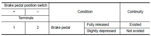
Is the inspection result normal? YES >> INSPECTION END
NO >> GO TO 2.
2.CHECK BRAKE PEDAL POSITION SWITCH-II
- Adjust brake pedal position switch installation. Refer to BR-15, "Adjustment".
- Check the continuity between brake pedal position switch terminals under the following conditions.
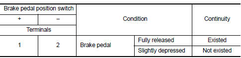
Is the inspection result normal? YES >> INSPECTION END
NO >> Replace brake pedal position switch. Refer to BR-22, "Exploded View".
 Sensor power supply 2 circuit
Description
ECM supplies a voltage of 5.0 V to some of the sensors systematically divided
into 2 groups, respectively.
Accordingly, when a short circuit develops in a sensor power source, a
ma ...
 ASCD Indicator
Component Function Check
1.CHECK ASCD INDICATOR FUNCTION
Check ASCD indicator under the following conditions.
ASCD INDICATOR
CONDITION
SPECIFICATION
CRUISE LAMP
Ig ...
Other materials:
Diagnosis system (ipdm e/r) (with intelligent key system)
Diagnosis description
Auto active test
Description
In auto active test, the IPDM E/R sends a drive signal to the following
systems to check their operation.
Front wiper (lo, hi)
Parking lamp
License plate lamp
Tail lamp
Front fog lamp (if equipped)
Headlamp (LO, HI)
A/C compress ...
Application Download
Once connected, the NissanConnectÔäó App will
search your phone to determine which compatible
applications are currently installed. The user
will then choose which apps they want to bring
into their vehicle from the list of apps within the
ÔÇťManage My AppsÔÇŁ section of the NissanConnect
Ôäó ...
Rear door
Door assembly
Door assembly : removal and installation
Caution:
Use two people when removing or installing the rear door assembly
due to its heavy weight.
When removing and installing rear door assembly, support rear door
with a suitable tool.
Removal
Remove rear door assembly h ...
