Nissan Sentra Service Manual: Sensor power supply 2 circuit
Description
ECM supplies a voltage of 5.0 V to some of the sensors systematically divided into 2 groups, respectively.
Accordingly, when a short circuit develops in a sensor power source, a malfunction may occur simultaneously in the sensors belonging to the same group as the shorted-circuit sensor.
Sensor power supply 1
- Battery current sensor
- Crankshaft position (CKP) sensor (POS)
- Throttle position (TP) sensor
- Accelerator pedal position (APP) sensor 1
NOTE:
If sensor power supply 1 circuit is malfunctioning, DTC P0643 is displayed.
Sensor power supply 2
- Camshaft position (CMP) sensor (PHASE)
- Mass air flow (MAF) sensor
- Engine oil pressure (EOP) sensor
- Exhaust valve timing (EVT) control position sensor
- Accelerator pedal position (APP) sensor 2
- Intake manifold runner control valve position sensor
Diagnosis Procedure
1.CHECK ACCELERATOR PEDAL POSITION SENSOR 2 POWER SUPPLY CIRCUIT-1
- Turn ignition switch OFF.
- Disconnect accelerator pedal position (APP) sensor harness connector.
- Turn ignition switch ON.
- Check the voltage between APP sensor harness connector and ground.
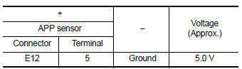
Is the inspection result normal? YES >> GO TO 4.
NO >> GO TO 2.
2.CHECK ACCELERATOR PEDAL POSITION SENSOR 2 POWER SUPPLY CIRCUIT-2
- Turn ignition switch OFF.
- Disconnect ECM harness connector.
- Turn ignition switch ON.
- Check the continuity between APP sensor harness connector and ECM.
CVT models
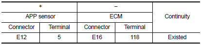
Is the inspection result normal? YES >> GO TO 3.
NO >> Repair or replace error-detected parts.
3.CHECK SENSOR POWER SUPPLY CIRCUITS
Check harness for short to power and short to ground, between the following terminals.
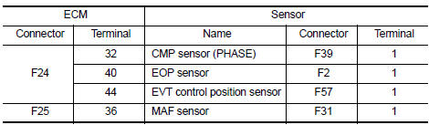
Is the inspection result normal? YES >> GO TO 4.
NO >> Repair or replace error-detected parts.
4.CHECK COMPONENTS
Check the following.
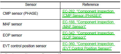
Is the inspection result normal? YES >> GO TO 5.
NO >> Repair or replace malfunctioning component.
5.CHECK APP SENSOR
Check APP sensor. Refer to EC-436, "Component Inspection (APP Sensor)".
Is the inspection result normal? YES >> Check intermittent incident. Refer to GI-39, "Intermittent Incident".
NO >> Replace accelerator pedal assembly. Refer to ACC-3, "Removal and Installation".
 P2138 APP Sensor
DTC Logic
DTC DETECTION LOGIC
NOTE:
If DTC P2138 is displayed with DTC P0643, first perform the trouble
diagnosis for DTC P0643. Refer to
EC-353, "DTC Logic".
DTC No.
CONSUL ...
 Brake pedal position switch
Component Function Check
1.CHECK BRAKE PEDAL POSITION SWITCH FUNCTION
With CONSULT
Turn ignition switch ON.
Select “ENGINE” using CONSULT.
Select “BRAKE SW1” in “DA ...
Other materials:
P1574 ASCD Vehicle speed sensor
Description
The ECM receives two vehicle speed sensor signals via CAN communication line.
One is sent from combination
meter, and the other is from TCM (Transmission control module). The ECM uses
these signals for ASCD
control. Refer to EC-51, "AUTOMATIC SPEED CONTROL DEVICE (ASCD) : Sys ...
Door lock and unlock switch
Component function check
1.Check function
Select door lock of bcm using consult.
Select cdl lock sw, cdl unlock sw in data monitor mode.
Check that the function operates normally according to the following
conditions.
Is the inspection result normal?
YES >> Main power windo ...
B1430, B1432 Seat belt pre-tensioner LH
Description
DTC B1430, B1432 SEAT BELT PRE-TENSIONER LH
The seat belt pre-tensioner LH is wired to the air bag diagnosis sensor unit.
The air bag diagnosis sensor unit
will monitor for opens and shorts in detected lines to the seat belt pre-tensioner
LH.
PART LOCATION
Refer to SRC-5, " ...
