Nissan Sentra Service Manual: P2138 APP Sensor
DTC Logic
DTC DETECTION LOGIC
NOTE:
If DTC P2138 is displayed with DTC P0643, first perform the trouble diagnosis for DTC P0643. Refer to EC-353, "DTC Logic".
| DTC No. | CONSULT screen terms (Trouble diagnosis content) | DTC detecting condition | Possible cause |
| P2138 | APP SENSOR (Throttle/Pedal position sensor/switch “D” / “E” voltage correlation) | Rationally incorrect voltage is sent to ECM compared with the signals from APP sensor 1 and APP sensor 2. |
|
DTC CONFIRMATION PROCEDURE
1.PRECONDITIONING
If DTC Confirmation Procedure has been previously conducted, always perform the following procedure before conducting the next test.
- Turn ignition switch OFF and wait at least 10 seconds.
- Turn ignition switch ON.
- Turn ignition switch OFF and wait at least 10 seconds.
TESTING CONDITION:
Before performing the following procedure, confirm that battery voltage is more than 8 V at idle.
>> GO TO 2.
2.PERFORM DTC CONFIRMATION PROCEDURE
- Start engine and let it idle for 1 second.
- Check DTC.
Is DTC detected? YES >> Proceed to EC-441, "Diagnosis Procedure".
NO >> INSPECTION END
Diagnosis Procedure
1.CHECK APP SENSOR 1 POWER SUPPLY
- Turn ignition switch OFF.
- Disconnect accelerator pedal position (APP) sensor harness connector.
- Turn ignition switch ON.
- Check the voltage between APP sensor harness connector and ground.
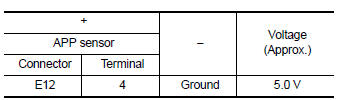
Is the inspection result normal? YES >> GO TO 3.
NO >> GO TO 2.
2.CHECK APP SENSOR 1 POWER SUPPLY CIRCUIT
- Turn ignition switch OFF.
- Disconnect ECM harness connector.
- Check the continuity between APP sensor harness connector and ECM harness connector.
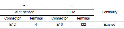
- Also check harness for short to ground.
Is the inspection result normal? YES >> Perform the trouble diagnosis for power supply circuit.
NO >> Repair or replace error-detected parts.
3.CHECK APP SENSOR 2 POWER SUPPLY
Check the voltage between APP sensor harness connector and ground.
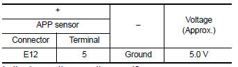
Is the inspection result normal? YES >> GO TO 5.
NO >> GO TO 4.
4.CHECK SENSOR POWER SUPPLY 2 CIRCUIT
Check sensor power supply 2 circuit. Refer to EC-444, "Diagnosis Procedure".
Is inspection result normal? YES >> Perform the trouble diagnosis for power supply circuit.
NO >> Repair or replace error-detected parts.
5.CHECK APP SENSOR GROUND CIRCUIT
- Turn ignition switch OFF
- Disconnect ECM harness connector.
- Check the continuity between APP sensor harness connector and ECM harness connector.
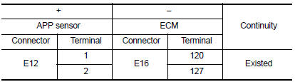
- Also check harness for short to power.
Is the inspection result normal? YES >> GO TO 6.
NO >> Repair or replace error-detected parts.
6.CHECK APP SENSOR INPUT SIGNAL CIRCUIT
- Check the continuity between APP sensor harness connector and ECM harness connector.
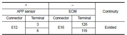
- Also check harness for short to ground and to power.
Is the inspection result normal? YES >> GO TO 7.
NO >> Repair or replace error-detected parts
7.CHECK APP SENSOR
Check APP sensor. Refer to EC-443, "Component Inspection (APP Sensor)".
Is the inspection result normal? YES >> Check intermittent incident. Refer to GI-39, "Intermittent Incident".
NO >> Replace accelerator pedal assembly. Refer to ACC-3, "Removal and Installation".
Component Inspection (APP Sensor)
1.CHECK ACCELERATOR PEDAL POSITION SENSOR
- Turn ignition switch OFF
- Reconnect all harness connectors disconnected.
- Turn ignition switch ON
- Check the voltage between ECM harness connector terminals as per the following condition.
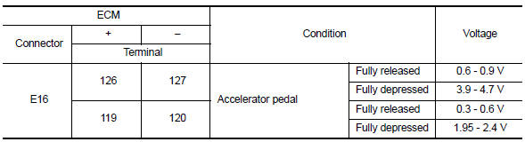
Is the inspection result normal? YES >> INSPECTION END
NO >> Replace accelerator pedal assembly. Refer to ACC-3, "Removal and Installation".
 2135 TP Sensor
DTC Logic
DTC DETECTION LOGIC
NOTE:
If DTC P2135 is displayed with DTC P0643, first perform the trouble
diagnosis for DTC P0643. Refer to
EC-353, "DTC Logic".
DTC No.
CONSUL ...
 Sensor power supply 2 circuit
Description
ECM supplies a voltage of 5.0 V to some of the sensors systematically divided
into 2 groups, respectively.
Accordingly, when a short circuit develops in a sensor power source, a
ma ...
Other materials:
Tire chains
CAUTION
Tire chains/cables should not be installed
on P205/50R17 size tires. Installation of
the tire chains/cables on P205/50R17 size
tires will cause damage to the vehicle. If
you plan to use tire chains/cables, you
should install P205/55R16 size tires on
your vehicle.
Use of tire chains m ...
Air conditioner operation (if so equipped)
Start the engine, turn the fan control dial to the
desired position, and press the
button to
activate the air conditioner. When the air conditioner
is on, cooling and dehumidifying functions
are added to the heater operation.
The air conditioner cooling function operates
only whe ...
U1001 can comm circuit
Description
CAN (Controller Area Network) is a serial communication line for real time
application. It is an on-vehicle multiplex
communication line with high data communication speed and excellent error
detection ability. Many electronic
control units are equipped onto a vehicle, and each co ...
