Nissan Sentra Service Manual: Bcm branch line circuit
Diagnosis procedure
1.Check connector
- Turn the ignition switch off.
- Disconnect the battery cable from the negative terminal.
- Check the terminals and connectors of the BCM for damage, bend and loose connection (unit side and connector side).
Is the inspection result normal? YES >> GO TO 2.
NO >> Repair the terminal and connector.
2.Check harness for open circuit
- Disconnect the connector of bcm.
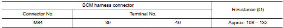
- Check the resistance between the bcm harness connector terminals.
- Without intelligent key system
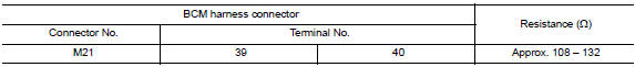
- With intelligent key system
Is the measurement value within the specification? YES >> GO TO 3.
NO >> Repair the BCM branch line.
3.Check power supply and ground circuit
Check the power supply and the ground circuit of the BCM. Refer to the following.
- With Intelligent Key system: Refer to BCS-67, "Diagnosis Procedure".
- Without intelligent key system: refer to bcs-120, "diagnosis procedure".
Is the inspection result normal? Yes (present error)>>replace the bcm. Refer to the following.
- With intelligent key system: refer to bcs-73, "removal and installation".
- Without Intelligent Key system: Refer to BCS-126, "Removal and Installation".
Yes (past error)>>error was detected in the bcm branch line.
No >> repair the power supply and the ground circuit.
 Strg branch line circuit
Diagnosis procedure
1.Check connector
Turn the ignition switch off
Disconnect the battery cable from the negative terminal.
Check the terminals and connectors of the steering angle sensor for ...
 Can communication circuit
Diagnosis procedure
1.Connector inspection
Turn the ignition switch OFF.
Disconnect the battery cable from the negative terminal.
Disconnect all the unit connectors on can communication syste ...
Other materials:
Wiring diagram
Brake control system
Wiring Diagram
...
Diagnosis system (ipdm e/r) (with intelligent key system)
Diagnosis description
Auto active test
Description
In auto active test, the IPDM E/R sends a drive signal to the following
systems to check their operation.
Front wiper (lo, hi)
Parking lamp
License plate lamp
Tail lamp
Front fog lamp (if equipped)
Headlamp (LO, HI)
A/C compress ...
Rear parcel shelf finisher
Exploded View
Seat belt finisher (RH)
Rear parcel shelf finisher
Rear seatback finisher (RH)
Top tether strap anchor finisher
(RH)
Top tether strap anchor finisher
(center)
Rear seatback finisher (LH)
Top tether strap anchor finisher
(LH)
Seat belt finisher (LH)
Seat b ...
