Nissan Sentra Service Manual: Strg branch line circuit
Diagnosis procedure
1.Check connector
- Turn the ignition switch off
- Disconnect the battery cable from the negative terminal.
- Check the terminals and connectors of the steering angle sensor for damage, bend and loose connection (unit side and connector side).
Is the inspection result normal? Yes >> go to 2.
No >> repair the terminal and connector.
2.Check harness for open circuit
- Disconnect the connector of steering angle sensor.
- Check the resistance between the steering angle sensor harness connector terminals.
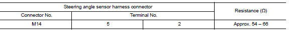
Is the measurement value within the specification? Yes >> go to 3.
No >> repair the steering angle sensor branch line.
3.Check power supply and ground circuit
Check the power supply and the ground circuit of the steering angle sensor. Refer to brc-44, "wiring diagram".
Is the inspection result normal? Yes (present error)>>replace the steering angle sensor. Refer to brc-113, "removal and installation".
Yes (past error)>>error was detected in the steering angle sensor branch line.
No >> repair the power supply and the ground circuit.
 M&A branch line circuit
Diagnosis procedure
1.Check connector
Turn the ignition switch off.
Disconnect the battery cable from the negative terminal.
Check the terminals and connectors of the combination meter for da ...
 Bcm branch line circuit
Diagnosis procedure
1.Check connector
Turn the ignition switch off.
Disconnect the battery cable from the negative terminal.
Check the terminals and connectors of the BCM for damage, bend and ...
Other materials:
B00A0 OCS System
Description
DTC B00A0 OCCUPANT CLASSIFICATION SYSTEM (OCS)
The OCS control unit is wired to the air bag diagnosis sensor unit. The air
bag diagnosis sensor unit will monitor
the OCS for failures and interruptions in communication between the OCS control
unit and the air bag
diagnosis sensor ...
C1155 BR Fluid level low
DTC Logic
Dtc detection logic
Dtc
Display item
Malfunction detected condition
Possible cause
C1155
C1155 br fluid level low
Brake fluid level is low or communication line between
the abs actuator and electric unit (control unit) and brake
fluid level switch is ...
Front power window motor
Removal and Installation
REMOVAL
Remove the front door glass regulator (2). Refer to GW-16,
"Removal and Installation".
Remove the bolts (A) and the front power window motor (1).
INSTALLATION
Installation is in the reverse order of removal. ...
