Nissan Sentra Service Manual: Wiring diagram
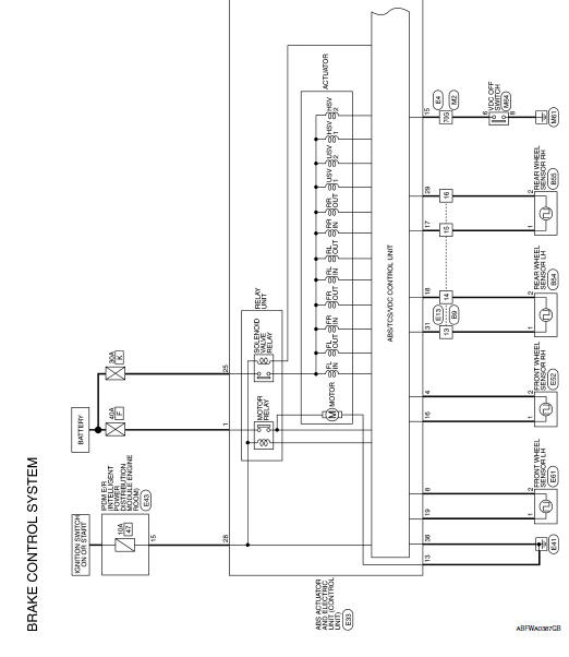
Brake control system
Wiring Diagram

 Ecu diagnosis information
Abs actuator and electric unit
(control unit)
Reference Value
VALUES ON THE DIAGNOSIS TOOL
CAUTION:
The display shows the control unit calculation data, so a
normal value might be displayed ev ...
 Basic inspection
...
Other materials:
P0452 EVAP Control system pressure sensor
DTC Logic
DTC DETECTION LOGIC
DTC No.
CONSULT screen terms
(Trouble diagnosis content)
DTC detecting condition
Possible cause
P0452
EVAP SYS PRES SEN
(Evaporative emission system
pressure sensor/switch low)
An excessively low voltage from the
sensor is se ...
Dtc/circuit diagnosis
Power supply and ground circuit
Diagnosis Procedure
Refer to LAN-7, "CAN COMMUNICATION SYSTEM : System Description".
Vehicle security indicator
Description
DTC DETECTION LOGIC
NOTE:
U1000 can be set if a module harness was disconnected and reconnected,
perhaps during a repair. Con ...
Precaution
Precaution for Supplemental Restraint System (SRS)
"AIR BAG" and "SEAT BELT PRE-TENSIONER"
The Supplemental Restraint System such as “AIR BAG” and “SEAT BELT PRE-TENSIONER”,
used along
with a front seat belt, helps to reduce the risk or severity of injur ...
