Nissan Sentra Service Manual: Ecu diagnosis information
Abs actuator and electric unit (control unit)
Reference Value
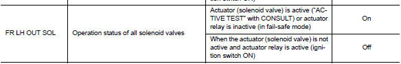
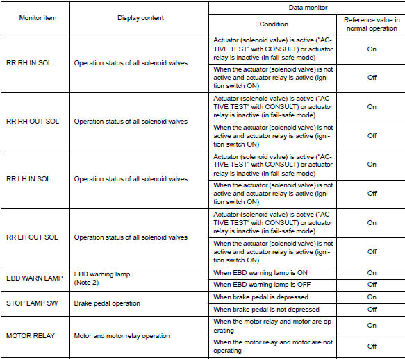
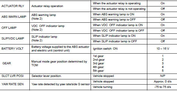
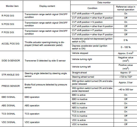
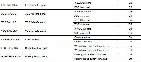
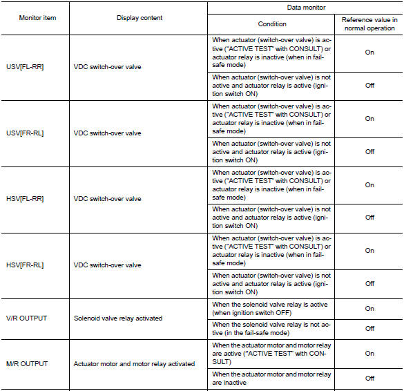
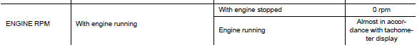
VALUES ON THE DIAGNOSIS TOOL
CAUTION:
The display shows the control unit calculation data, so a normal value might be displayed even in the event the output circuit (harness) is open or short-circuited.
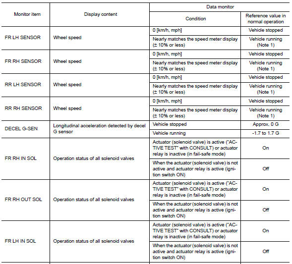
Note 1:
Confirm tire pressure is normal. Note 2
: On and off timing for warning lamps and indicator lamps.
-
Refer to BRC-22, "VDC/TCS/ABS : VDC Function".
-
Refer to BRC-24, "VDC/TCS/ABS : TCS Function".
-
Refer to BRC-26, "VDC/TCS/ABS : ABS Function".
-
Refer to BRC-27, "VDC/TCS/ABS : EBD Function".
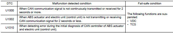
Fail-safe
VDC AND TCS FUNCTIONS
VDC warning lamp in combination meter turns ON when a malfunction occurs in system [ABS actuator and electric unit (control unit)]. The control is suspended for VDC and TCS functions. However, ABS and EBD functions operate normally.
ABS FUNCTION
ABS warning lamp and SLIP indicator lamp in combination meter turn ON when a malfunction occurs in system [ABS actuator and electric unit (control unit)]. The control is suspended for VDC, TCS and ABS functions.
However, EBD functions operate normally.
EBD FUNCTION
ABS warning lamp, brake warning lamp and SLIP indicator lamp in combination meter turn ON when a malfunction occurs in system [ABS actuator and electric unit (control unit)]. The control is suspended for VDC, TCS, ABS and EBD functions.
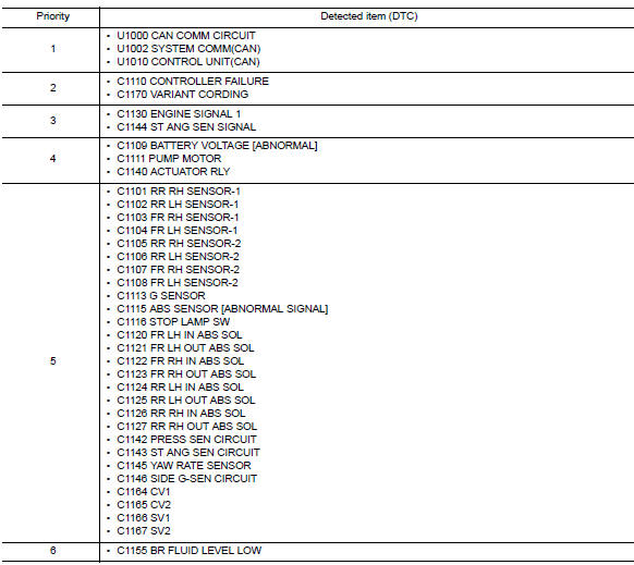
DTC Inspection Priority Chart
When multiple DTCs are displayed simultaneously, check each one using the following priority list.
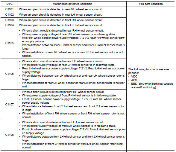
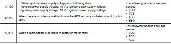
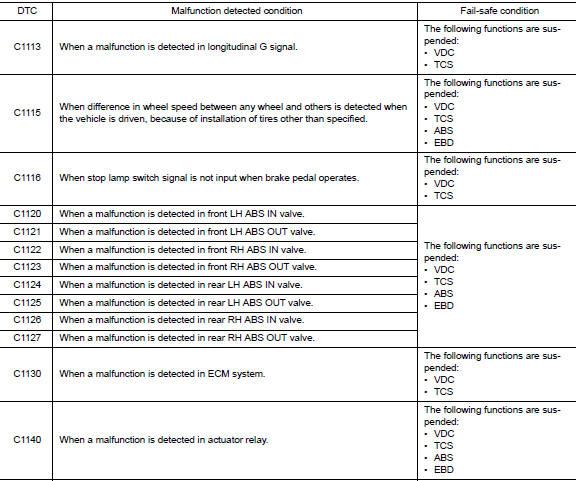
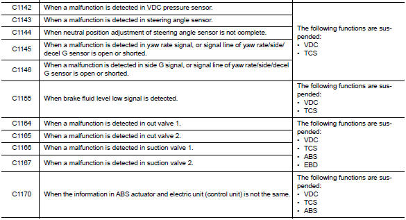
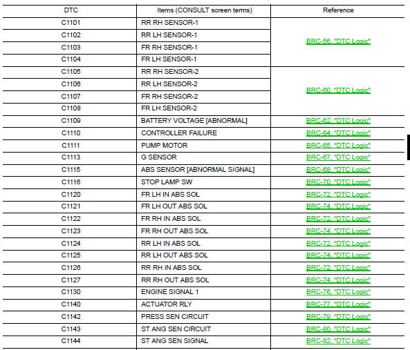
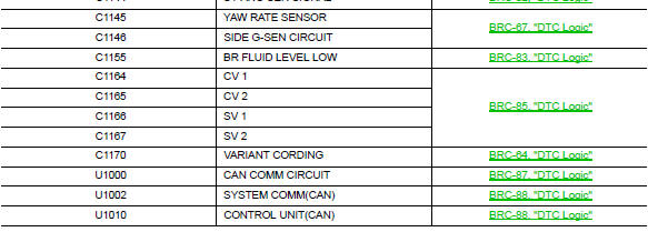
DTC Index
 Diagnosis system [abs actuator and electric unit (control
unit)]
Diagnosis system [abs actuator and electric unit (control
unit)]
CONSULT Function (ABS)
FUNCTION
CONSULT can display each diagnostic item using the following
direct diagnostic modes.
Direct Diagnostic Mode
Description
ECU identification
T ...
 Wiring diagram
Brake control system
Wiring Diagram
...
Other materials:
Application Download
Once connected, the NissanConnect™ App will
search your phone to determine which compatible
applications are currently installed. The user
will then choose which apps they want to bring
into their vehicle from the list of apps within the
“Manage My Apps” section of the NissanConnect
™ ...
Preparation
Special Service Tool
The actual shape of the tools may differ from those illustrated here.
Commercial Service Tool
Clip list
Descriptions for Clips
Replace any clips which are damaged during removal or installation.
...
Liquid Gasket
REMOVAL OF LIQUID GASKET SEALING
After removing the bolts and nuts, separate the mating surface and
remove the liquid gasket using Tool (A).
Tool Number : KV10111100 (J-37228)
CAUTION:
Be careful not to damage the mating surfaces.
In areas where the cutter is difficult to use, use ...
