Nissan Sentra B18 (2020-2025) Service Manual: Wiper & Washer :: Removal and Installation
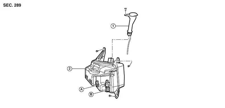
Washer Tank. With Washer Level Switch
Exploded View
Exploded View
|
1. |
Washer tank inlet |
2. |
Washer tank |
A. |
Washer level switch (not serviced separately) |
|
B. |
Washer tank pump (not serviced separately |
Removal and Installation
Removal and Installation
REMOVAL
Remove the washer tank inlet.
Remove the front combination lamp (RH). Refer to Removal and Installation (Halogen Headlamp) or Removal and Installation (LED Headlamp).
Disconnect the harness connectors from the washer pump and washer level switch.
Disconnect the washer tube from the washer pump.
Remove the washer tank bolts and the washer tank.
INSTALLATION
Installation is in the reverse order of removal.
Note:
-
After installation, add water to the top of the washer tank inlet to check that no leaks exist.
-
Fill washer tank with specified amount of fluid. Refer to Specifications.
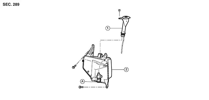
Without Washer Level Switch
Exploded View
Exploded View
|
1. |
Washer tank inlet |
2. |
Washer tank |
A. |
Washer tank pump (not serviced separately) |
Removal and Installation
Removal and Installation
REMOVAL
Remove the washer tank inlet.
Remove the front combination lamp (RH). Refer to Removal and Installation (Halogen Headlamp) or Removal and Installation (LED Headlamp).
Disconnect the harness connector from the washer pump.
Disconnect the washer tube from the washer pump.
Remove the washer tank bolts and the washer tank.
INSTALLATION
Installation is in the reverse order of removal.
Note:
-
After installation, add water to the top of the washer tank inlet to check that no leaks exist.
-
Fill washer tank with specified amount of fluid. Refer to Specifications.
Washer Pump. Removal and Installation. Removal and Installation
Removal and Installation
For removal and installation of the washer pump, refer to Removal and Installation(with washer level switch) or Removal and Installation(without washer level switch).
Washer Fluid Level Switch. Removal and Installation. Removal and Installation
Removal and Installation
For removal and installation of the washer level switch, refer to Removal and Installation.
Washer Nozzle Tube. Exploded View
Exploded View
WITHOUT WASHER LEVEL SWITCH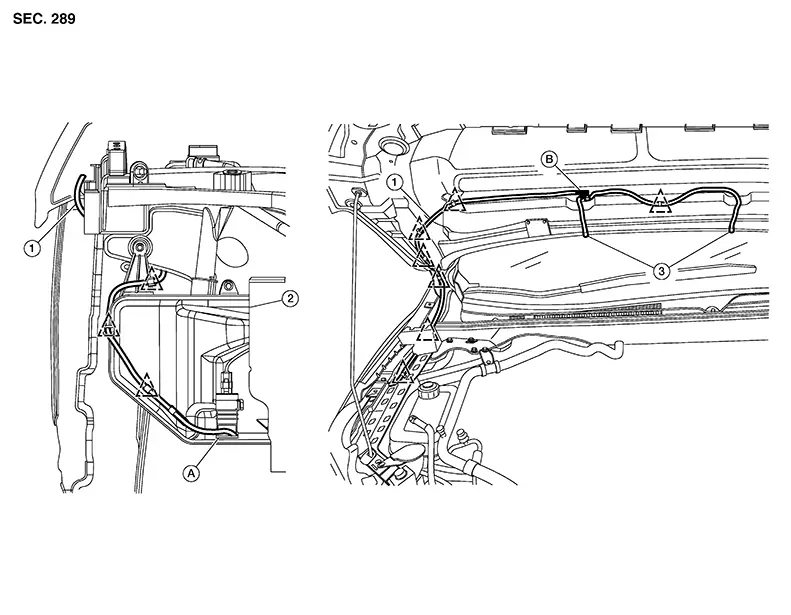
|
1. |
Washer tube |
2. |
Washer tank |
3. |
Washer nozzle (LH/RH) |
|
A. |
Washer pump (not serviced separately) |
B. |
Check valve |
|
Clip |

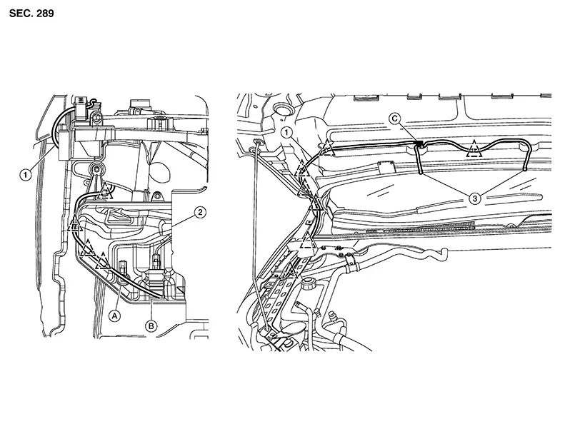
|
1. |
Washer tube |
2. |
Washer tank |
3. |
Washer nozzle (LH/RH) |
|
A. |
Washer level switch (not serviced separately) |
B. |
Washer pump (not serviced separately) |
C. |
Check valve |
|
|
Clip |
Washer Nozzle
Removal and Installation
Removal and Installation
REMOVAL
Disconnect
the washer nozzle from the hood by pushing on the nozzle as
shown.
 :
Front
:
Front
Disconnect the washer tube from the washer nozzle.
Remove the washer nozzle.
INSTALLATION
Installation is in the reverse order of removal.
CAUTION:
Adjust the nozzle spray pattern. Refer to Adjustment.
Adjustment
Adjustment
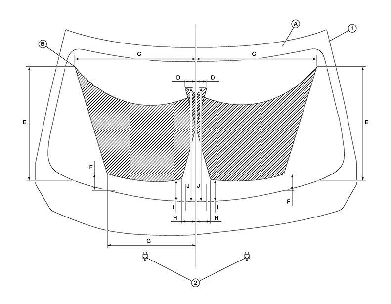
|
1. |
Windshield glass |
2. |
Washer nozzle (LH/RH) |
A. |
Black print |
|
B. |
Spray pattern |
C. |
555.5 mm (21.87 in) |
D. |
51.3 mm (2.02 in) |
|
E. |
514.4 mm (20.25 in) |
F. |
77.3 mm (3.04 in) |
G. |
403.8 mm (15.90 in) |
|
H. |
65.6 mm (2.58 in) |
J. |
96.9 mm (3.81 in) |
K. |
512.7 mm (20.18 in) |
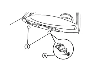
Insert a suitable tool into the nozzle hole (A).
Move
up/down and left/right to adjust the spray position of each nozzle
(1). 
Washer Tube
Removal and Installation
Removal and Installation
REMOVAL
Partially remove the front fender protector (RH). Refer to Exploded View.
Remove the hood insulator. Refer to Exploded View.
Disconnect
the washer nozzle tubes (1) and (2) from check valve (A). 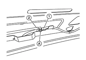
Disconnect the washer tube from the washer pump.
Remove the washer tube from the clips and remove the washer tube.
INSTALLATION
Installation is in the reverse order of removal.
Note:
Fill washer tank with specified amount of fluid. Refer to Specifications.
Front Wiper Arm. Exploded View
Exploded View
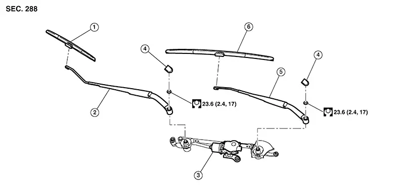
|
1. |
Wiper blade (RH) |
2. |
Wiper arm (RH) |
3. |
Wiper drive assembly |
|
4. |
Wiper arm cover |
5. |
Wiper arm (LH) |
6. |
Wiper blade (LH) |
Removal and Installation
Removal and Installation
REMOVAL
Remove the wiper arm cover.
Remove the wiper arm nut.
Raise the wiper arm, then remove the wiper arm.
INSTALLATION
Clean the
wiper arm mount as shown.
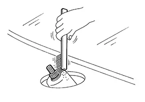 Note:
Note:
This will reduce the possibility of wiper arm looseness.
Install the wiper arm.
Install the wiper arm nut.
Install the wiper arm cover.
Check that the wiper blades stop at the park position.
Wiper Blade. Removal and Installation. Removal and Installation
Removal and Installation
REMOVAL
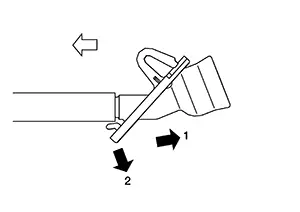
Lift the wiper arm away from the windshield glass.
Rotate the
wiper blade and push the release tab (A), then move the wiper blade
down (B) the wiper arm. 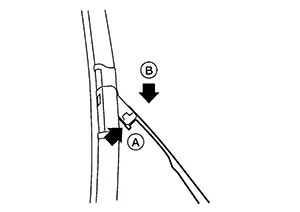
Remove the wiper blade.
INSTALLATION
Insert the wiper blade onto the wiper arm and slide it up until it clicks into place.
Rotate the wiper blade so the dimple is in the groove.
Lay the wiper arm back down on the windshield.
Place ignition switch ON and operate the windshield wipers to ensure the repair has been completed properly.
Check that the wiper blade contacts the windshield properly; otherwise the wiper arm may be damaged from wind pressure while driving.
Front Wiper Drive Assembly. Exploded View
Exploded View
|
1. |
Wiper blade (RH) |
2. |
Wiper arm (RH) |
3. |
Wiper drive assembly |
|
4. |
Wiper nut cap |
5. |
Wiper arm (LH) |
6. |
Wiper blade (LH) |
Removal and Installation
Removal and Installation
REMOVAL
Remove the cowl top. Refer to Removal and Installation.
Disconnect the harness connector from the wiper drive assembly.
Remove the wiper drive assembly bolts.
Remove the wiper drive assembly.
INSTALLATION
Install the wiper drive assembly.
Tighten the
wiper drive assembly bolts to specification in the sequence
shown.
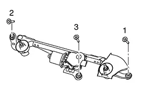
|
Bolts |
: 8 Nm (0.82 kg-m, 71 in-lb) |
Connect the harness connector to the wiper drive assembly.
Install the cowl top. Refer to Removal and Installation.
Check the operation of the wiper blades and that they stop at the normal position.
Wiper and Washer Switch. Removal and Installation. Removal and Installation
Removal and Installation
For removal and installation of the wiper and washer switch, refer to Removal and Installation.
Other materials:
Operation
Switch Name and Function
Switch Name
and Function
OPERATION AND DISPLAY OF AUTOMATIC AIR CONDITIONING
SYSTEM
Display: Display in A/C switch assembly
Air conditioning operation status is indicated
on display in A/C switch assembly.
Air conditioni ...
Dtc/circuit Diagnosis
C1b80-54 Control Module
Dtc Description
DTC Description
DTC DETECTION LOGIC
DTC No.
CONSULT screen terms
(Trouble diagnosis
content)
...
P0139 Ho2s2
Dtc Description
DTC Description
The heated oxygen sensor 2 has a much longer switching time
between rich and lean than the air fuel ratio (A/F) sensor 1. The oxygen storage
capacity of the three way catalyst 1 causes the longer switching time. To judge
the malfunctions of heated oxy ...