Nissan Sentra B18 (2020-2025) Service Manual: Wheel Side
Removal and Installation
REMOVAL
Remove disc brake rotor. Refer to Removal and Installation.
CAUTION:
Do not depress the brake pedal while the brake caliper is removed.
Remove the wheel sensor bolt. Position the wheel sensor and the wheel sensor harness aside. Refer to Removal and Installation.
CAUTION:
Do not pull or twist the harness when removing.
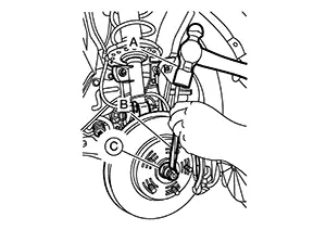
Using hammer (A) and Tool (B) release staked area (C) of wheel hub lock nut (D).
|
Tool number (B) |
: (NI-52982) |
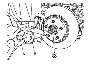
Visually verify that staked area
(A) of wheel hub lock nut (B) is completely released from front drive
shaft (1) or damage to drive shaft can occur. 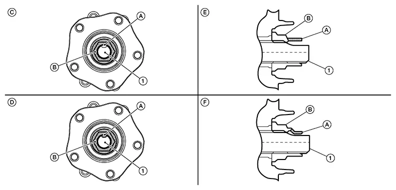
|
(C) |
: Fully released |
|
(D) |
: Not fully released |
|
(E) |
: Fully released (sectional view) |
|
(F) |
: Not fully released (sectional view) |
Warning:
To avoid risk of death or severe personal injury:
-
Be sure that staked area of wheel hub lock nut is fully released or damage to drive shaft can occur.
-
Do not damage front drive shaft threads.
Hold the wheel hub and bearing using
Tool (A). Loosen the wheel hub lock nut.
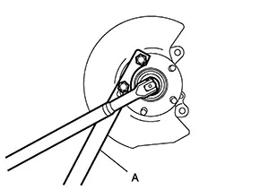
|
Tool (A) number |
: KV40104000 (ŌĆāŌĆöŌĆā) |
Using a piece of wood and a suitable
tool, tap on the wheel hub lock nut to disengage the drive shaft from
the wheel hub and bearing. 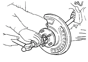
CAUTION:
-
Do not place the drive shaft joint at an extreme angle. Also be careful not to overextend slide joint.
-
Do not allow the drive shaft to hang down without support.

Use a suitable puller if the drive shaft cannot be separated from the wheel hub and bearing even after performing the above procedure.
Remove the wheel hub lock nut.
Remove the nut and bolt from the lower ball joint. Disconnect the steering knuckle from the transverse link.
Remove the drive shaft from the wheel hub and bearing.
Remove the boot bands.
Separate the boot from the joint sub-assembly.
Screw a suitable tool (A) into the
joint sub-assembly screw part to a length of 30 mm (1.18 in) or more.
Support the drive shaft with one hand and pull out the joint sub-assembly
from the shaft. 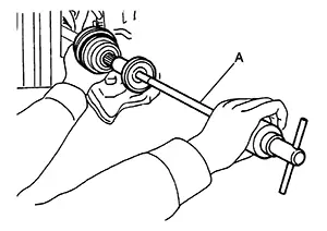
CAUTION:
-
Align the suitable tool and the drive shaft. Remove the joint sub-assembly by pulling firmly and uniformly.
-
If the joint sub-assembly cannot be pulled out, try after removing the drive shaft from the Nissan Sentra vehicle. Refer to Removal and Installation (LH)or Removal and Installation (RH).
Remove the circular clip (1) from
the shaft. 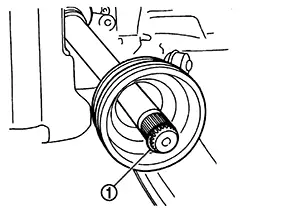
Remove the outer boot from the shaft.
INSTALLATION
Clean the old grease from the joint sub-assembly using paper shop cloths.
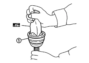
Fill the serration slot on the joint
sub-assembly (1) with NISSAN Genuine grease or equivalent until the
serration slot and ball groove become full to the brim.
CAUTION:
After applying the grease, use paper shop cloths to wipe off the grease that has oozed out.
Note:
Always check with the Parts Department for the latest parts information.
Install the outer boot and the boot bands to the shaft.
CAUTION:
-
Wrap the serration on the shaft with tape to protect the boot from damage.
-
Do not reuse the boot.
-
Do not reuse the boot bands.
Remove the tape wrapped around the serration on the shaft.
Position the circular clip (1) on
the groove at the shaft edge.
CAUTION:
Do not reuse the circular clip.
Note:
A drive joint inserter is recommended when installing the circular clip.
Align with the shaft and the joint sub-assembly. Assemble the shaft with the joint sub-assembly while holding the circular clip.
Install the joint sub-assembly (1)
to the shaft using a suitable tool.
Warning:
-
Ensure that the circular clip is properly engaged, otherwise the joint sub-assembly could pull away from the transaxle during Nissan Sentra vehicle operation resulting in loss of drive force and possible drive shaft damage, which may cause a crash and serious injury or damage the drive shaft.
Pull the joint sub-assembly in the axial direction away from transaxle. Confirm that the joint sub assembly cannot be pulled out.
Apply the specified amount of grease
to the inside of the large diameter side of the boot.
Note:
Always check with the Parts Department for the latest parts information.
|
Grease amount |
: Refer to Drive Shaft. |
Install the boot securely into the
grooves (indicated by ŌĆ£*ŌĆØ marks) as shown.
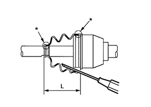
CAUTION:
If there is grease on the boot mounting surfaces (indicated by ŌĆ£*ŌĆØ marks) on the shaft or the joint sub-assembly, the boot may come off. Remove all grease from the boot mounting surfaces.
To prevent the deformation of the boot, adjust the boot installation length to the specified value by inserting a suitable tool into the inside of the boot from the large diameter side of the boot and discharging the inside air.
|
Boot installation length (L) |
: Refer to Drive Shaft. |
CAUTION:
-
The boot may break if the boot installation length is not correct.
-
Be careful not to touch the inside of the boot with the tip of the suitable tool.
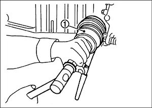
Install new large and small boot
bands securely using Tool (A).
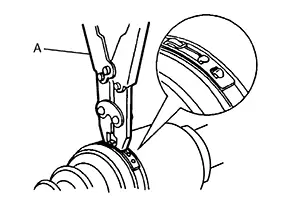
CAUTION:
Do not reuse the boot bands.
|
Tool number |
(A): KV40107300 (NI-51751) |
Secure the boot band so that dimension
(A) meets the specification.
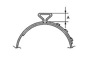
|
Dimension (A) |
: Refer to Drive Shaft. |
Attempt to rotate the boot to check whether or not the boot bands are securing the boot. If the boot is not secure, remove the boot bands, reposition the boot, and install new boot bands.
Clean the mating surfaces of the wheel hub lock nut and the wheel hub assembly.
CAUTION:
Do not apply lubricating oil to these mating surfaces.
Apply a moderate coat of paste [service parts (440037S000)] to bearing surface (A) as shown.
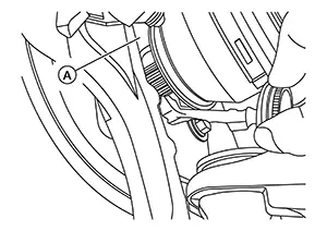 Note:
Note:
Always check with the Parts Department for the latest parts information.
Install the drive shaft to the wheel hub and bearing. Temporarily install, but do not tighten, the wheel hub lock nut.
CAUTION:
Do not reuse the wheel hub lock nut.
Install the transverse link to the steering knuckle with the nut and bolt. Refer to Exploded View.
Hold the wheel hub and bearing using suitable tool. Tighten the wheel hub lock nut.
|
Wheel hub lock nut |
165 N┬Ęm (17 kgŌłÆm, 122 ftŌłÆlb) |
CAUTION:
-
Since the drive shaft is assembled by press-fitting, use a torque wrench to tighten the wheel hub lock nut. Do not use a power tool.
-
Be sure to use torque wrench to tighten the wheel hub lock nut. Never use a power tool.
-
Do not reuse wheel hub lock nut.
-
Too much torque causes axle noise. Too little torque causes wheel bearing looseness. Tighten the wheel hub lock nut to the specification.
Wheel hub lock nut tightening torque does not over torque for avoiding axle noise, and does not less than torque for avoiding looseness.
|
Tool number |
: KV40104000 (ŌĆāŌĆöŌĆā) |
-
Using hammer (A) and cold chisel (B) stake the wheel hub lock nut (C) as shown.
Warning:
To avoid the risk of death or severe personal injury:
-
Use the following range when staking the wheel hub lock nut.
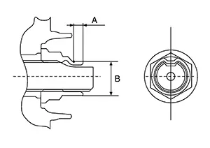
(A)
: 6.2 mm (0.244 in)
(B)
: 26.4 - 27.8 mm (1.039 - 1.094 in)
-
Install the wheel sensor, the wheel sensor bolt, and the wheel sensor harness. Refer to Removal and Installation.
Align the matching marks (A) on
the disc brake rotor and on the wheel hub and bearing. Install the
disc brake rotor.
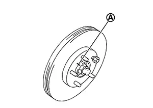
CAUTION:
Do not drop the disc brake rotor.
Remove the wire from the brake caliper. Install the brake caliper and the brake caliper torque member bolts. Refer to Removal and Installation.
CAUTION:
Do not twist the brake hose.
Install the wheel and tire. Refer to Removal and Installation.
Complete the inspection. Refer to Inspection.
 Exploded View
Exploded View
LH
1.
Circular clip
2.
...
 Transaxle Side
Removal and Installation
Removal and
Installation
REMOVAL
Remove front drive shaft. Refer
to Removal and Installation (LH) or Removal and Installation (RH).
Secure front drive shaf ...
Other materials:
Dtc Index
DTC Index
Note:
The details of time display are as follows:
CRNT: A malfunction is detected now
PAST: A malfunction was detected in the past
├Ś:Applicable
Self diagnostic
result
...
Trouble Diagnosis Without Consult
Trouble Diagnosis without CONSULT
DIAGNOSIS MODE
Note:
Diagnosis Mode can not be entered if a
malfunction is not detected in User Mode.
CONSULT
Ignition switch ON.
After AIR BAG warning lamp lights for 7 seconds,
ignition switch OFF within 1 second. ...
Exploded View
Exploded View
1.
Rear body side welt
2.
Rear pillar upper
finisher
3.
...
