Nissan Sentra B18 (2020-2025) Service Manual: Transaxle Side
Removal and Installation
REMOVAL
Remove front drive shaft. Refer to Removal and Installation (LH) or Removal and Installation (RH).
Secure front drive shaft in a vise.
CAUTION:
When securing shaft in a vise, always use copper or aluminum plates between vise and shaft.
Remove boot bands and slide boot back.
CAUTION:
Do not reuse boot bands.
Put matching marks on the slide joint housing and shaft before separating the slide joint housing.
CAUTION:
Use paint or an equivalent for matching marks. Do not scratch surfaces.
Pull out slide joint housing.
Put matching marks (A) on spider
assembly and shaft.
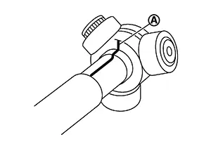
CAUTION:
Use paint or an equivalent for matching marks. Do not scratch surfaces.
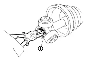
Remove snap ring (1) using a suitable tool.
CAUTION:
Do not reuse stopper ring.
Remove spider assembly from shaft.
Remove boot from shaft.
CAUTION:
Do not reuse boot.
Remove circular clip from slide joint housing.
CAUTION:
Do not reuse circular clip.
Remove dust shield from slide joint housing.
CAUTION:
Do not reuse dust shield.
Clean old grease off slide joint housing.
INSTALLATION
Installation is in the reverse order of removal.
-
When installing the front drive shaft, apply a moderate coat of paste [service parts (440037S000)] to bearing surface (A) as shown.
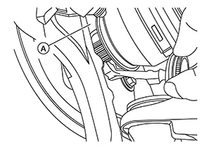 Note:
Note: 
Always check with the Parts Department for the latest parts information.
CAUTION:
-
Do not reuse boot.
-
Do not reuse circular clip.
-
Do not reuse boot.
-
Do not reuse stopper ring.
Inspection
INSPECTION AFTER INSTALLATION
Check the wheel sensor harness to be sure the connectors are fully seated.
Check the wheel alignment. Refer to Inspection.
 Wheel Side
Removal and Installation
Removal and
Installation
REMOVAL
Remove disc brake rotor. Refer to Removal and Installation.
CAUTION:
Do not depress the brake pedal while the brake
...

Other materials:
Preparation
Special Service Tools
The actual shape of the tools may differ from those illustrated here.
Commercial Service Tools
Clip list
Descriptions for Clips
Replace any clips which are damaged during removal or installation.
...
P0327, P0328 KS
DTC Logic
DTC DETECTION LOGIC
DTC No.
CONSULT screen terms
(Trouble diagnosis content)
DTC detecting condition
Possible cause
P0327
KNOCK SEN/CIRC-B1
(Knock sensor 1 circuit
low bank 1)
An excessively low voltage from the knock sensor
is sent to ECM.
...
Exploded View
Exploded View
Exploded View
1.
Stabilizer bar
2.
Stabilizer clamp
3.
...
