Nissan Sentra B18 (2020-2025) Service Manual: Water Hose
Exploded View
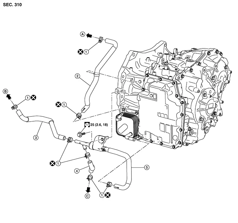
Exploded View
|
1. |
Hose clamp |
2. |
Water hose A |
3. |
Water hose B |
|
4. |
Water hose C |
5. |
Heater thermostat housing |
A. |
To water outlet. Refer to Exploded View. |
|
B. |
To water pump. Refer to Exploded View. |
C. |
To oil cooler. Refer to Exploded View. |
. |
Removal and Installation
Removal and Installation
REMOVAL
Warning:
Do not remove the radiator cap when the engine is hot. Serious burns could occur from high pressure coolant escaping from the radiator. Wrap a thick cloth around the cap. Slowly turn it a quarter turn to allow built-up pressure to escape. Carefully remove the cap by turning it all the way.
CAUTION:
Perform when the engine is cold.
Note:
When removing components such as hoses, tubes/lines, etc., cap or plug openings to prevent fluid from spilling.
Remove front under cover. Refer to Removal and Installation.
Remove hose clamps, and remove CVT water hose A.
Remove hose clamps, and remove CVT water hose B.
Remove hose clamps, and remove CVT water hose C.
Remove hose clamps and bolt, then remove heater thermostat housing.
INSTALLATION
Installation is in the reverse order of removal.
CAUTION:
-
Do not reuse hose clamp and clip.
-
Securely install the water hose clip to the converter housing.
-
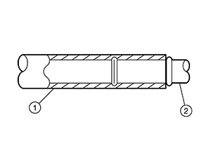
Refer to the following when installing water hoses.
Hose (1)
Installation side tube (2)
Direction of paint mark
Hose insertion depth
Water hose A
Water outlet
Matches with protrusion of water-outlet or rearward
Hose end reaches end of water-outlet tube
CVT oil warmer
Align with mark on CVT oil warmer or frontward
Hose end reaches the 2-stage bulge
Water hose B
Water pump
Frontward
Heater thermostat housing
Water hose C
Heater thermostat housing
Oil cooler
Heater thermostat housing
Water pump
Oil cooler
CVT oil warmer
-
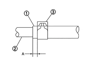
Refer to the followings when installing hose clamp.
CAUTION:
Hose clamp should not interfere with the bulge of tube.
Hose (1)
Installation side tube (2)
Hose clamp (3)
Direction of tab
Clamping position (A)
Water hose A
Water outlet
Align with mark on water hose or rearward
5 – 7 mm (0.20 – 0.28 in) from hose end
CVT oil warmer
Align with mark on water hose or frontward
Water hose B
Water pump
Frontward
Heater thermostat housing
Water hose C
Heater thermostat housing
Oil cooler
Heater thermostat housing
Water pump
Oil cooler
CVT oil warmer
Inspection
Inspection
INSPECTION AFTER INSTALLATION
Start the engine.
Check visually that there is no leakage of engine coolant.
Other materials:
Removal and Installation. 8ch Can Gateway
8ch Can Gateway
Removal and Installation
Removal and Installation
CAUTION:
If replacing 8CH CAN gateway, Perform "ADDITIONAL
SERVICE WHEN REPLACING 8CH CAN GATEWAY". Refer to Work Procedure.
REMOVAL
Remove
instrument panel assembly. Refer to Removal and Installation ...
6m/t
Exploded View (lh)
Exploded View
(LH)
1.
Circular clip
2.
Slide joint housing
3.
...
Interior Lighting System. Symptom Diagnosis. Interior Lighting System Symptoms. Symptom Table
Interior Lighting System Symptoms. Symptom Table
Symptom Table
Symptom Table
Note:
Perform the self-diagnosis with CONSULT before
the symptom diagnosis. Perform the trouble diagnosis if any DTC is
detected.
Symptom
...