Nissan Sentra B18 (2020-2025) Service Manual: 6m/t
Exploded View (lh)
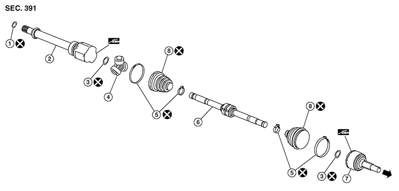
Exploded View (LH)
|
1. |
Circular clip |
2. |
Slide joint housing |
3. |
Snap ring |
|
4. |
Spider assembly |
5. |
Boot band |
6. |
Shaft |
|
7. |
Joint sub-assembly |
8. |
Boot |
|
Wheel side |
Disassembly and Assembly (lh)
Disassembly and Assembly (LH)
DISASSEMBLY (WHEEL SIDE)
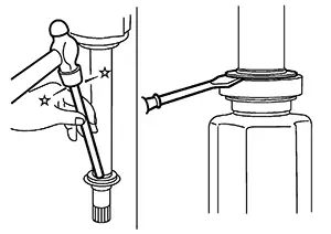
Secure the drive shaft in a vise.
CAUTION:
When securing the drive shaft in a vise, always use aluminum or copper plates between the vise and the drive shaft.
Remove the boot bands and slide the boot back.
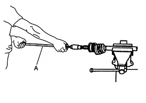
Screw a
suitable tool (A) into the joint sub-assembly screw part to a
length of 30 mm (1.18 in) or more. Support the drive shaft with one
hand and pull out the joint sub-assembly from the shaft.
CAUTION:
-
Align the suitable tool and the drive shaft. Remove the joint sub-assembly by pulling firmly and uniformly.
-
If the joint sub-assembly cannot be removed after five or more attempts, replace the shaft and the joint sub-assembly as a set.
Remove the circular clip from the shaft.
Remove the outer boot from the shaft.
Inspect the components. Refer to Inspection (RH).
DISASSEMBLY (TRANSAXLE SIDE)
Secure the drive shaft in a vise.
CAUTION:
When securing the drive shaft in a vise, always use aluminum or copper plates between the vise and the drive shaft.
Remove the boot bands and slide the boot back.
Put matching marks on the slide joint housing and on the shaft.
CAUTION:
Use paint or an equivalent for matching marks. Do not scratch the surfaces.
Remove the slide joint housing from the shaft.
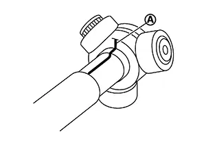
Put
matching marks (A) on the spider assembly and on the shaft.
CAUTION:
Use paint or an equivalent for matching marks. Do not scratch the surfaces.
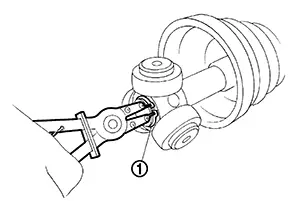
Remove the
snap ring (1).
Remove the spider assembly from the shaft.
Remove the inner boot from the shaft.
Remove the dust shield from the slide joint housing.
Remove the circular clip from the slide joint housing.
Clean the old grease from the slide joint housing with paper shop cloths.
Inspect the components. Refer to Inspection (RH).
INSPECTION AFTER DISASSEMBLY
Check the following items and replace the part if necessary.
Shaft
Check the shaft for runout, cracks, or other damage. Replace the entire drive shaft if necessary.
Dynamic Damper
Check the dynamic damper for cracks or wear. Replace the entire drive shaft if necessary.
Joint Sub-Assembly
Check the following:
-
Joint sub-assembly for rough rotation and excessive axial looseness.
-
The inside of the joint sub-assembly for entry of foreign material.
-
Joint sub-assembly for compression scars, cracks, and fractures inside of the joint sub-assembly.
Replace the entire drive shaft if there are any non-standard conditions of components.
Housing and spider assembly
Replace the entire drive shaft if there is scratching or wear of the housing roller contact surface or the spider roller contact surface.
Support Bearing (RH) (if equipped)
Verify the support bearing rolls freely and is free from noise, cracks, pitting or wear. Replace the entire drive shaft if there are any non-standard conditions.
Support Bearing Bracket (RH) (if equipped)
Check the support bearing bracket for cracks or damage. Replace the support bearing bracket if there are any non-standard conditions.
ASSEMBLY (WHEEL SIDE)
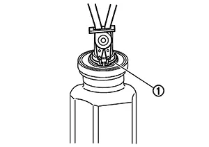
Clean the old grease from the joint sub-assembly using paper shop cloths.
Fill the
serration slot on the joint sub-assembly (1) with NISSAN genuine
grease or equivalent until the serration slot and ball groove
become full to the brim.
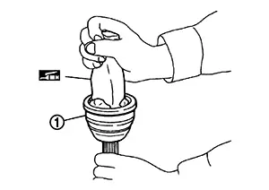
CAUTION:
After applying the grease, use paper shop cloths to wipe off the grease that has oozed out.
Note:
Always check with the Parts Department for the latest parts information.
Install the
outer boot and the boot bands to the shaft.
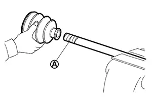
CAUTION:
-
Wrap the serration on the shaft with tape (A) to protect the boot from damage.
-
Do not reuse the boot.
-
Do not reuse the boot bands.
Remove the tape wrapped around the serration on the shaft.
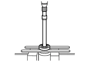
Position
the circular clip (1) on the groove at the shaft edge.
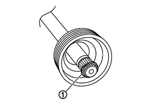
CAUTION:
Do not reuse the circular clip.
Note:
A drive joint inserter is recommended when installing the circular clip.
Align both center axles with the shaft edge and the joint sub-assembly. Assemble the shaft with the joint sub-assembly while holding the circular clip.
Install the
joint sub-assembly to the shaft using a suitable tool.
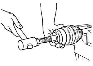
CAUTION:
-
Make sure the circular clip is properly positioned on the groove of the joint sub-assembly.
-
Confirm that the joint sub-assembly is correctly engaged while rotating the drive shaft.
Apply the
specified amount of grease to the inside of the large diameter side
of the boot.
Note:
Always check with the Parts Department for the latest parts information.
|
Grease amount |
: Refer to Drive Shaft. |
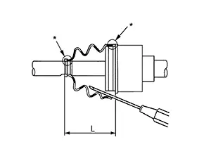
Install the
boot securely into the grooves (indicated by “*” marks)
as shown.
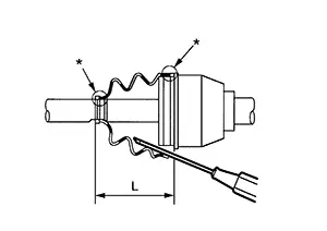
CAUTION:
If there is grease on the boot mounting surfaces (indicated by “*” marks) on the shaft or the joint sub-assembly, the boot may come off. Remove all grease from the boot mounting surfaces.
To prevent the deformation of the boot, adjust the boot installation length to the specified value by inserting a suitable tool into the inside of the boot from the large diameter side of the boot and discharging the inside air.
|
Boot installation length (L) |
: Refer to Drive Shaft. |
CAUTION:
-
The boot may break if the boot installation length is not correct.
-
Be careful not to touch the inside of the boot with the tip of the suitable tool.
Install new
large and small boot bands securely using Tool (A).
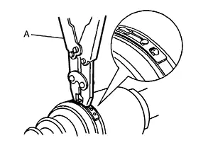
CAUTION:
Do not reuse the boot bands.
|
Tool number |
(A): KV40107300 (NI-51751) |
Secure the
boot band so that dimension (A) meets the specification.
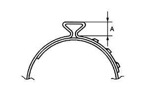
|
Dimension (A) |
: Refer to Drive Shaft. |
Attempt to rotate the boot to check whether or not the boot bands are securing the boot. If the boot is not secure, remove the boot bands, reposition the boot, and install new boot bands.
ASSEMBLY (TRANSAXLE SIDE)
Install the
inner boot and the boot bands to the shaft.
CAUTION:
-
Wrap the serration on the shaft with tape (A) to protect the boot from damage.
-
Do not reuse the boot.
-
Do not reuse the boot bands.
Remove the tape wrapped around the serration on the shaft.
Align the
matching mark (A) on the spider assembly (1) with the matching mark
on the shaft (2). Install the spider assembly to the shaft with the
chamfer (B) facing the shaft.
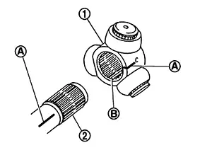
Secure the
spider assembly onto the shaft with the snap ring (1).
CAUTION:
Do not reuse the snap ring.
Apply the
appropriate amount of grease (Genuine NISSAN Grease or equivalent)
to the spider assembly and to the sliding surface.
Note:
Always check with the Parts Department for the latest parts information.
Install the slide joint housing onto the spider assembly and pack the balance of the specified amount grease (Genuine NISSAN Grease or equivalent) into the slide joint housing.
|
Grease amount |
: Refer to Drive Shaft. |
Align the matching marks on the slide joint housing and on the shaft.
Install the
boot securely into the grooves (indicated by “*” marks)
as shown.
CAUTION:
If there is grease on the boot mounting surfaces (indicated by “*” marks) on the shaft or the joint sub-assembly, the boot may come off. Remove all grease from the boot mounting surfaces.
To prevent the deformation of the boot, adjust the boot installation length to the specified value by inserting a suitable tool into the inside of the boot from the large diameter side of the boot and discharging the inside air.
|
Boot installation length (L) |
: Refer to Drive Shaft. |
CAUTION:
-
The boot may break if the boot installation length is not correct.
-
Be careful not to touch the inside of the boot with the tip of the suitable tool.
Install the boot bands securely.
CAUTION:
Do not reuse the boot bands.
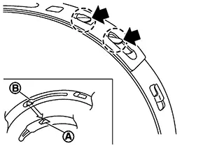
Put boot band in the groove on drive shaft boot. Then fit pawls into holes to temporary installation. Note:
For the large diameter side, fit projection (A) and guide slit (B) at first.
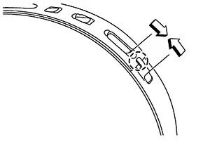
 Pinch
projection on the band with suitable pliers to tighten band. Insert the tip of band into the
lower part of pawl (marked with dotted circle) as shown.
Pinch
projection on the band with suitable pliers to tighten band. Insert the tip of band into the
lower part of pawl (marked with dotted circle) as shown.
Attempt to rotate the boot to check whether or not the boot bands are securing the boot. If the boot is not secure, remove the boot bands, reposition the boot, and install new boot bands.
Install the dust shield to the slide joint housing.
CAUTION:
Do not reuse the dust shield.
Install the circular clip to the slide joint housing.
Warning:
Ensure that the circular clip is properly engaged, otherwise the joint sub-assembly could pull away from the transaxle during Nissan Sentra vehicle operation resulting in loss of drive force and possible driveshaft damage, which may cause a crash and serious injury or damage to the driveshaft.
Exploded View (rh)
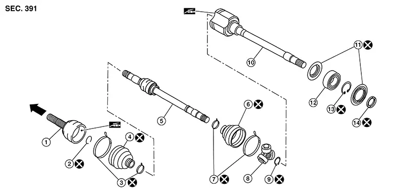
Exploded View (RH)
|
1. |
Joint sub-assembly |
2. |
Circular clip |
3. |
Boot band |
|
4. |
Boot |
5. |
Shaft |
6. |
Boot |
|
7. |
Boot band |
8. |
Spider assembly |
9. |
Snap ring |
|
10. |
Slide joint housing |
11. |
Dust shield |
12. |
Support bearing |
|
13. |
Snap ring |
14. |
Dust shield |
|
Wheel side |
Disassembly and Assembly (rh)
Disassembly and Assembly (RH)
DISASSEMBLY (WHEEL SIDE)
Secure the drive shaft in a vise.
CAUTION:
When securing the drive shaft in a vise, always use aluminum or copper plates between the vise and the drive shaft.
Remove the boot bands and slide the boot back.
Screw a
suitable tool (A) into the joint sub-assembly screw part to a
length of 30 mm (1.18 in) or more. Support the drive shaft with one
hand and pull out the joint sub-assembly from the shaft.
CAUTION:
-
Align the suitable tool and the drive shaft. Remove the joint sub-assembly by pulling firmly and uniformly.
-
If the joint sub-assembly cannot be removed after five or more attempts, replace the shaft and the joint sub-assembly as a set.
Remove the circular clip from the shaft.
Remove the outer boot from the shaft.
Inspect the components. Refer to Inspection (RH).
DISASSEMBLY (TRANSAXLE SIDE)
Secure the drive shaft in a vise.
CAUTION:
When securing the drive shaft in a vise, always use aluminum or copper plates between the vise and the drive shaft.
Remove the boot bands and slide the boot back.
Put matching marks on the slide joint housing and on the shaft.
CAUTION:
Use paint or an equivalent for matching marks. Do not scratch the surfaces.
Remove the slide joint housing from the shaft.
Put
matching marks (A) on the spider assembly and on the shaft.
CAUTION:
Use paint or an equivalent for matching marks. Do not scratch the surfaces.
Remove the
snap ring (1).
Remove the spider assembly from the shaft.
Remove the inner boot from the shaft.
Remove the
support bearing using the following procedure:
Remove the dust shields from the
slide joint housing.
 Remove the snap ring (1).
 Press
out the support bearing from the slide joint housing.
Press
out the support bearing from the slide joint housing.
 Remove the dust shield from the
slide joint housing.
Remove the dust shield from the
slide joint housing.
Clean the old grease from the slide joint housing with paper shop cloths.
Inspect the components. Refer to Inspection (RH).
INSPECTION AFTER DISASSEMBLY
Check the following items and replace the part if necessary.
Shaft
Check the shaft for runout, cracks, or other damage. Replace the entire drive shaft if necessary.
Dynamic Damper
Check the dynamic damper for cracks or wear. Replace the entire drive shaft if necessary.
Joint Sub-Assembly
Check the following:
-
Joint sub-assembly for rough rotation and excessive axial looseness.
-
The inside of the joint sub-assembly for entry of foreign material.
-
Joint sub-assembly for compression scars, cracks, and fractures inside of the joint sub-assembly.
Replace the entire drive shaft if there are any non-standard conditions of components.
Housing and spider assembly
Replace the entire drive shaft if there is scratching or wear of the housing roller contact surface or the spider roller contact surface.
Support Bearing (RH) (if equipped)
Verify the support bearing rolls freely and is free from noise, cracks, pitting or wear. Replace the entire drive shaft if there are any non-standard conditions.
Support Bearing Bracket (RH) (if equipped)
Check the support bearing bracket for cracks or damage. Replace the support bearing bracket if there are any non-standard conditions.
ASSEMBLY (WHEEL SIDE)
Clean the old grease from the joint sub-assembly using paper shop cloths.
Fill the
serration slot on the joint sub-assembly (1) with NISSAN genuine
grease or equivalent until the serration slot and ball groove
become full to the brim.
CAUTION:
After applying the grease, use paper shop cloths to wipe off the grease that has oozed out.
Note:
Always check with the Parts Department for the latest parts information.
Install the
outer boot and the boot bands to the shaft.
CAUTION:
-
Wrap the serration on the shaft with tape (A) to protect the boot from damage.
-
Do not reuse the boot.
-
Do not reuse the boot bands.
Remove the tape wrapped around the serration on the shaft.
Position
the circular clip (1) on the groove at the shaft edge.
CAUTION:
Do not reuse the circular clip.
Note:
A drive joint inserter is recommended when installing the circular clip.
Align both center axles with the shaft edge and the joint sub-assembly. Assemble the shaft with the joint sub-assembly while holding the circular clip.
Install the
joint sub-assembly to the shaft using a suitable tool.
CAUTION:
-
Make sure the circular clip is properly positioned on the groove of the joint sub-assembly.
-
Confirm that the joint sub-assembly is correctly engaged while rotating the drive shaft.
Apply the
specified amount of grease to the inside of the large diameter side
of the boot.
Note:
Always check with the Parts Department for the latest parts information.
|
Grease amount |
: Refer to Drive Shaft. |
Install the
boot securely into the grooves (indicated by “*” marks)
as shown.
CAUTION:
If there is grease on the boot mounting surfaces (indicated by “*” marks) on the shaft or the joint sub-assembly, the boot may come off. Remove all grease from the boot mounting surfaces.
To prevent the deformation of the boot, adjust the boot installation length to the specified value by inserting a suitable tool into the inside of the boot from the large diameter side of the boot and discharging the inside air.
|
Boot installation length (L) |
: Refer to Drive Shaft. |
CAUTION:
-
The boot may break if the boot installation length is not correct.
-
Be careful not to touch the inside of the boot with the tip of the suitable tool.
Install new
large and small boot bands securely using Tool (A).
CAUTION:
Do not reuse the boot bands.
|
Tool number |
(A): KV40107300 (NI-51751) |
Secure the
boot band so that dimension (A) meets the specification.
|
Dimension (A) |
: Refer to Drive Shaft. |
Attempt to rotate the boot to check whether or not the boot bands are securing the boot. If the boot is not secure, remove the boot bands, reposition the boot, and install new boot bands.
ASSEMBLY (TRANSAXLE SIDE)
Install the support bearing using the following procedure: Install the dust shield to the slide joint housing.
CAUTION:
Do not reuse the dust shield.
Press the support bearing (1) onto the slide joint housing using the suitable tool (A).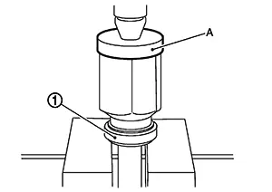
CAUTION:
Do not reuse the support bearing.
Install the snap ring (1).
CAUTION:
Do not reuse the snap ring.
Install the dust shields.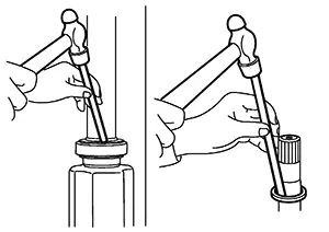
CAUTION:
Do not reuse the dust shield.
Install the
inner boot and the boot bands to the shaft.
CAUTION:
-
Wrap the serration on the shaft with tape (A) to protect the boot from damage.
-
Do not reuse the boot.
-
Do not reuse the boot bands.
Remove the tape wrapped around the serration on the shaft.
Align the
matching mark (A) on the spider assembly (1) with the matching mark
on the shaft (2). Install the spider assembly to the shaft with the
chamfer (B) facing the shaft.
Secure the
spider assembly onto the shaft with the snap ring (1).
CAUTION:
Do not reuse the snap ring.
Apply the
appropriate amount of grease (Genuine NISSAN Grease or equivalent)
to the spider assembly and to the sliding surface.
Note:
Always check with the Parts Department for the latest parts information.
Install the slide joint housing onto the spider assembly and pack the balance of the specified amount grease (Genuine NISSAN Grease or equivalent) into the slide joint housing.
|
Grease amount |
: Refer to Drive Shaft. |
Align the matching marks on the slide joint housing and on the shaft.
Install the
boot securely into the grooves (indicated by “*” marks)
as shown.
CAUTION:
If there is grease on the boot mounting surfaces (indicated by “*” marks) on the shaft or the joint sub-assembly, the boot may come off. Remove all grease from the boot mounting surfaces.
To prevent the deformation of the boot, adjust the boot installation length to the specified value by inserting a suitable tool into the inside of the boot from the large diameter side of the boot and discharging the inside air.
|
Boot installation length (L) |
: Refer to Drive Shaft. |
CAUTION:
-
The boot may break if the boot installation length is not correct.
-
Be careful not to touch the inside of the boot with the tip of the suitable tool.
Install the boot bands securely.
CAUTION:
Do not reuse the boot bands.
Put boot band in the groove on drive shaft boot. Then fit pawls into holes to temporary installation. Note:
For the large diameter side, fit projection (A) and guide slit (B) at first.
Pinch
projection on the band with suitable pliers to tighten band. Insert the tip of band into the
lower part of pawl (marked with dotted circle) as shown.
Attempt to rotate the boot to check whether or not the boot bands are securing the boot. If the boot is not secure, remove the boot bands, reposition the boot, and install new boot bands.
Other materials:
Component Parts
Exterior Lighting System
Component Parts Location
Component Parts
Location
A.
View of instrument panel
B.
M/T transmi ...
B Terminal Circuit. Diagnosis Procedure
Diagnosis Procedure
Diagnosis Procedure
“B” terminal circuit supplies power to charge the
battery and to operate the vehicles electrical system.
CHECK “B” TERMINAL CONNECTION
Ignition switch OFF.
...
Front Camera Unit
Values on the Diagnosis Tool
Values On The Diagnosis Tool
Note:
The following table includes information (items)
inapplicable to this Nissan Sentra vehicle. For information (items) applicable to this
vehicle, refer to CONSULT display items.
...