Nissan Sentra B18 (2020-2025) Service Manual: Differential Side Oil Seal
Exploded View
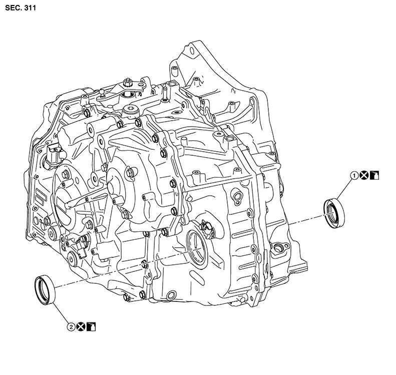
Exploded View
|
1. |
Differential side oil seal (transaxle case side) |
2. |
Differential side oil seal (converter housing side) |
Removal and Installation
Removal and Installation
REMOVAL
Note:
When removing components such as hoses, tubes/lines, etc., cap or plug openings to prevent fluid from spilling.
Remove front drive shaft. Refer to Removal and Installation (LH) or Removal and Installation (RH).
Remove differential side oil seal
(1) using suitable tool (A). 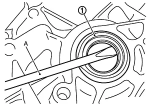
CAUTION:
Be careful not to scratch transaxle case and converter housing.
INSTALLATION
Installation is in the reverse order of removal.
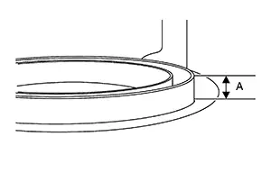
Measure lip height (A) and determine
differential side oil seal insertion reference value (B) from the
list to calculate lip protrusion (C). 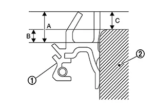
|
(1) |
: Differential side oil seal |
|
(2) |
: Converter housing or transaxle case |
|
Lip protrusion (C) |
: C=A–B |
|
Differential side oil seal insertion reference value (B): |
|
|
Transaxle case side |
: 1.8 mm (0.071 in) |
|
Converter housing side |
: 2.2 mm (0.087 in) |
CAUTION:
-
Do not reuse differential side oil seal.
-
Put a mark on the measurement area and measure height of seal lip at four points diagonally using suitable tool.
Since seal lips have a tolerance of ± 0.3 mm (± 0.012 in) at maximum due to manufacturing tolerances or packing conditions, it is necessary to measure the seal lip height beforehand to clarify the tolerance.
As an indicator of the parallelism
and insertion depth, cut a masking tape (1) to specified width [add
1 mm (0.04 in) to the value calculated from the tip of differential
side oil seal lip] and affix to the differential side oil seal. 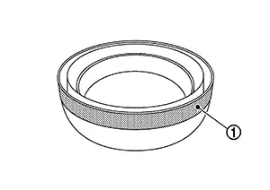
Install the differential side oil seal, using Tools.
|
Tool number |
: :KV31501200 (NI–52281) |
|
Tool number |
: :KV31500910 (NI–52282) |
|
Tool number |
: :ST35325000 (NI–8092) |
CAUTION:
-
If differential side oil seal is inserted deeper than the reference value, use a new differential side oil seal and perform the steps again.
-
Apply CVT fluid to the differential side oil seal lip and around the oil seal.
Remove masking tape.
Adjust as instructed below to optimize the protrusion size and parallelism.
CAUTION:
If differential side oil seal is inserted deeper than the reference value, use a new differential side oil seal and perform the steps again.
-
Protrusion size (A)
CAUTION:
Protrusion must fall within ± 0.5 mm (0.020 in) of calculated size.
-
Parallelism at four diagonal points (
 )
)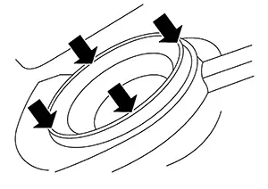
CAUTION:
The difference among four diagonal points must be within 0.3 mm (0.012 in).
Note:
If differential side oil seal is uneven while installing, tilt suitable tool.
Check that the protrusion size and parallelism are adequate.
Inspection and Adjustment
Inspection and Adjustment
INSPECTION AFTER INSTALLATION
Drive the vehicle and check visually that there is no leakage of CVT fluid. Refer to Inspection.
ADJUSTMENT AFTER INSTALLATION
Adjust the CVT fluid level. Refer to Adjustment.
Other materials:
Intelligent Key Button Operation Has Poor Range (one Key)
Description
Description
Intelligent Key button operation has poor range.
(One Intelligent Key has the symptom, other keys operate
normally.)
SYMPTOM TABLE (ONE INTELLIGENT KEY HAS THE
SYMPTOM, OTHER KEYS OPERATE NORMALLY)
...
Trunk Opener Request Switch
Component Function Check
Component Function Check
CHECK FUNCTION
CONSULT
Select "Request switch BD/TR" in "Data Monitor"
mode of "BCM(TRUNK)".
Select that the functi ...
Exterior. Symptom Diagnosis. Squeak and Rattle Trouble Diagnoses
Squeak and Rattle Trouble Diagnoses
Work Flow
Work Flow
CUSTOMER INTERVIEW
Interview the customer if possible, to determine
the conditions that exist when the noise occurs. Use the Diagnostic
Worksheet during the interview to document the facts and conditions
when the noise occu ...