Nissan Sentra Service Manual: Unit disassembly and assembly
Steering gear and linkage
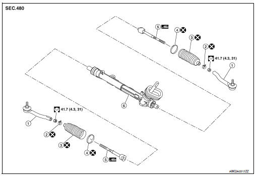
Exploded View
-
Outer socket
-
Boot clamp (small diameter)
-
Boot
-
Boot clamp (large diameter)
-
Inner socket
-
Gear housing assembly
Disassembly and Assembly
DISASSEMBLY
-
Loosen outer socket lock nut, and remove outer socket.
CAUTION:
When loosening lock nut, be sure to fix outer socket with a wrench or an equivalent.
-
Remove boot clamps, and then remove boot from inner socket.
CAUTION:
-
Do not damage inner socket part and gear housing part of steering gear assembly when removing boot. steering gear assembly must be replaced if steering gear assembly are damaged because it may cause foreign material interfusion.
-
Do not reuse boot clamps.
-
Remove inner socket.
ASSEMBLY
-
Apply recommended grease to inner socket (A) of gear housing assembly, and install boot to gear housing assembly.
Use Genuine Lithium Soap, Autorex A (manufactured by Kyodo yushi) or equivalent.
CAUTION:
Do not reuse boot.
Grease application position (Reference) (B) : 10 mm (0.39 in)
-
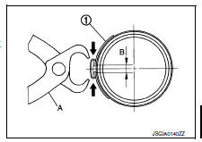
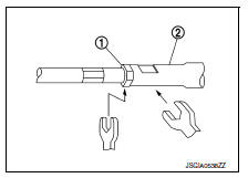
Install boot clamp (large diameter) (1) to boot using Tool.
CAUTION:
-
Do not reuse boot clamp (large diameter).
-
Install boot clamp (large diameter) securely to boot groove, and crimp it so as to have clearance (B) of 3 mm (0.12 in) or less as shown.
Tool number (A) : KV40107300 ( — )
-
Install boot clamp (small diameter) to boot.
CAUTION:
Do not reuse boot clamp (small diameter).
-
Adjust inner socket to standard length (L), and then tighten outer socket lock nut (1) to the specified torque. Check length again after tightening lock nut.
(L) : Refer to ST-19, "Power Steering Gear".
CAUTION:
-
When tightening the outer socket lock nut (1), be sure to fix outer socket (2) with suitable tool to prevent the ball joint from getting contact with the knuckle.
-
Adjust toe-in after this procedure. The length achieved after toe-in adjustment is not necessary the above value.
 Steering gear and linkage
Exploded View
REMOVAL
Steering gear assembly
Front suspension member
Front
Removal and Installation
REMOVAL
Set steering wheel to the straight-ahead position.
Remove ...
 Service data and specifications (SDS)
Steering Wheel
Steering Angle
Steering Column
STEERING COLUMN LENGTH
TILT MECHANISM OPERATING RANGE
Power Steering Gear
STEERING OUTER SOCKET AND INNER SOCKET
RACK STROKE
...
Other materials:
P0461 Fuel level sensor
DTC Logic
DTC DETECTION LOGIC
NOTE:
If DTC P0461 is displayed with DTC UXXXX, first perform the trouble
diagnosis for DTC UXXXX.
If DTC P0461 is displayed with DTC P0607, first perform the trouble
diagnosis for DTC P0607. Refer
to EC-350, "DTC Logic".
Driving long distan ...
Removal and installation
Audio unit
Exploded view
Audio unit
Audio unit bracket (LH)
Audio unit bracket (rh)
Removal and installation
Removal
Disconnect the negative battery terminal. Refer to pg-50, "removal and
installation (battery)".
Remove cluster lid c lower. Refer to ip-20, "re ...
Periodic maintenance
M/T OIL
Inspection
OIL LEAKAGE
Make sure that gear oil is not leaking from transaxle or around it.
OIL LEVEL
Remove filler plug (1) and gasket from transaxle case.
Check the oil level from filler plug mounting hole as shown.
CAUTION:
Do not start engine while checking oil level.
Se ...
