Nissan Sentra B18 (2020-2025) Service Manual: Tire Pressure Monitoring System
System Description
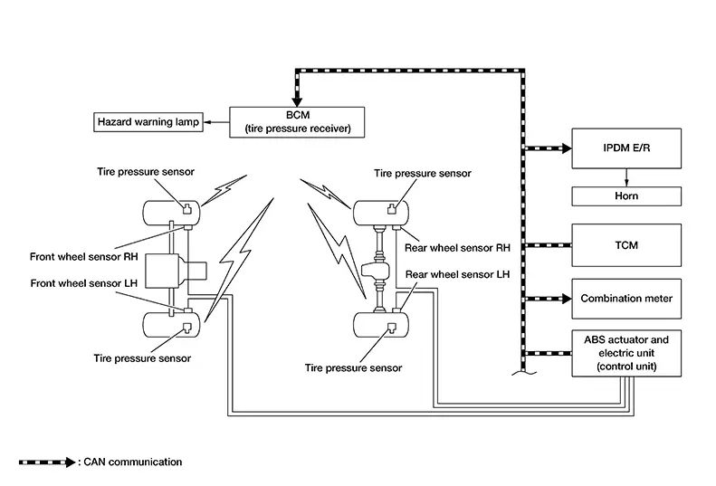
SYSTEM DIAGRAM
INPUT SIGNAL AND OUTPUT SIGNAL
Major signal transmission between each unit via communication lines is shown in the following table:
|
Component parts |
Signal item |
|---|---|
|
BCM |
Mainly receives the following signal from the ABS actuator and electric unit (control unit) via CAN communication:
Mainly receives the following signal from the TCM via CAN communication (with CVT):
Mainly receives the following signal from the IPDM E/R via CAN communication (with M/T):
Mainly transmits the following signals to the combination meter via CAN communication:
Mainly transmits the following signal to the IPDM E/R via CAN communication:
|
|
Combination meter |
Mainly receives the following signals from the BCM via CAN communication:
|
|
ABS actuator and electric unit (control unit) |
Mainly transmits the following signal to the BCM via CAN communication:
|
|
TCM |
Mainly transmits the following signal to the BCM via CAN communication (with CVT):
|
|
IPDM E/R |
Mainly receives the following signal from the BCM via CAN communication:
Mainly transmits the following signal to the BCM via CAN communication (with M/T):
|
DESCRIPTION
-
During driving, the BCM receives the signal transmitted from the tire pressure sensor installed in each wheel. The BCM of this system has pressure judgment and trouble diagnosis functions. When the TPMS (Tire Pressure Monitoring System) detects low inflation pressure or another unusual symptom, the low tire pressure warning lamp in the combination meter turns ON.
-
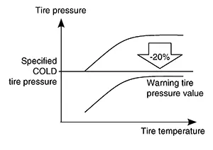
Tire pressure varies as per the change in tire temperature. Therefore, warning tire pressure value is varied as per the change in tire temperature.
-
If the tire pressure is less than the warning tire pressure value, the low tire pressure warning lamp illuminates.
-
Location of the wheel is specified due to the synchronism of the wheel sensor position and tire pressure sensor position.
-
Activates TPMS when the Nissan Sentra vehicle speed is 25 MPH (40 km/h) or more.
-
TPMS has Easy Fill Tire Alert function to aid in tire inflation. Refer to System Description.
LOW TIRE PRESSURE WARNING LAMP INDICATION CONDITION
Uses CAN communication from the BCM to illuminate the low tire pressure warning lamp on the combination meter.
|
Name |
Design |
Layout |
|---|---|---|
|
Low tire pressure warning lamp |
|
For layout, refer to Design (type A) or Design (type B). |

|
Condition |
Low tire pressure warning lamp |
|---|---|
|
Ignition switch OFF |
OFF |
|
Ignition switch ON (system normal) |
Warning lamp turns on for 1 second, then turns off. |
|
Low tire pressure |
ON |
|
Configuration not performed in TPMS |
Warning lamp blinks 1 min, then turns on. |
|
Tire pressure sensor ID not registered in BCM |
|
|
TPMS malfunction (other diagnostic item) |
HAZARD WARNING LAMP INDICATION CONDITION
The hazard warning lamp blinks under the following conditions:
-
When ID registration is completed. Refer to Work Procedure.
-
During the use of the Easy Fill Tire Alert function.
HORN CONTROL CONDITION
During the use of Easy Fill Tire Alert function.
 System
...
 Low Tire Pressure Warning
System Description
System Description
SYSTEM DIAGRAM
INPUT SIGNAL AND OUTPUT SIGNAL
Major signal transmission between each unit via
communication is shown in the following table:
...
Other materials:
Receiving a call
When a call is placed to the connected phone,
the display will change to phone mode.
To accept the incoming call, either:
Press the button on
the steering
wheel, or
Touch the green phone icon on the screen.
To reject the incoming call, either:
Press the button on the
...
P10c0 Internal Control Module Fuel Injector
Dtc Description
DTC Description
DTC DETECTION LOGIC
DTC
CONSULT screen terms
(Trouble diagnosis
content)
DTC detection
condition
...
Exploded View
Exploded View
1.
Vacuum hose
2.
Hose clamp
3.
Brake booster
...
