Nissan Sentra B18 (2020-2025) Service Manual: Tcu
Values on the Diagnosis Tool

The following table includes information (items) inapplicable to this Nissan Sentra vehicle. For information (items) applicable to this vehicle, refer to CONSULT display items.
|
Monitor Item |
Condition |
Value/Status |
|
|---|---|---|---|
|
USB |
Ignition switch ON |
Con |
|
|
SIM status |
Ignition switch ON |
Unlock |
|
|
Backup battery age |
Ignition switch ON |
Display backup battery age (days) |
|
|
eUICC STATUS PIN used |
Ignition switch ON |
Enable |
|
|
SOS switch |
Ignition switch ON |
When pressing SOS switch |
On |
|
Except for above |
Off |
||
|
Zone |
Ignition switch ON |
U.S.A |
|
|
Power type |
Ignition switch ON |
Engine |
|
|
Brand |
Ignition switch ON |
INFINITI |
|
|
Radio wave |
Ignition switch ON |
On |
|
Reference Value
TERMINAL LAYOUT
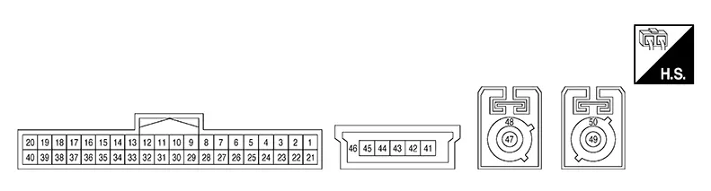
PHYSICAL VALUES
|
Terminal (Wire color) |
Description |
Condition |
Reference value (Approx.) |
||
|---|---|---|---|---|---|
|
+ |
– |
Signal name |
Input/Output |
||
|
1 (B) |
29 (B) |
Battery power supply |
Input |
Ignition switch OFF |
Battery Voltage |
|
5 (BG) |
28 (B) |
SOS switch LED signal |
Input |
Ignition switch ACC
|
0 V |
|
Ignition switch ACC
|
5 V |
||||
|
6 (LA/SB) |
— |
CAN-High |
Input/Output |
— |
— |
|
7 (LA/V) |
— |
CAN-Low |
Input/Output |
— |
— |
|
10 (W) |
29 (B) |
Ignition signal |
Input |
Ignition switch ON |
Battery Voltage |
|
12 (B) |
28 (B) |
Microphone output signal |
Output |
Ignition switch ACC
|
 |
|
17 (V) |
28 (B) |
Microphone signal |
Input |
Ignition switch ACC
|
|
|
18 (LG) |
28 (B) |
Microphone VCC |
Input |
Ignition switch ACC |
5 V |
|
26 (LA/SB) |
— |
AV communication high |
Input/Output |
— |
— |
|
27 (LA/LG) |
— |
AV communication low |
Input/Output |
— |
— |
|
28 (B) |
Ground |
Ground |
— |
Ignition switch ON |
0 V |
|
29 (B) |
Ground |
Ground |
— |
Ignition switch ON |
0 V |
|
31 (W) |
32 (B) |
Sound signal (+) |
Output |
Ignition switch ACC
|
|
|
37 (G) |
28 (B) |
SOS call switch signal |
Input |
Ignition switch ACC
|
0 V |
|
Ignition switch ACC
|
5 V |
||||
|
41 (B) |
— |
Ground |
— |
— |
— |
|
43 (G) |
— |
D+ signal |
Input/Output |
— |
— |
|
44 (W) |
— |
D- signal |
Input/Output |
— |
— |
|
45 (R) |
— |
V BUS signal |
Input |
— |
— |
|
46 (Shield) |
— |
Shield |
— |
— |
— |
|
47 (B) |
Ground |
TEL antenna signal |
Input |
TEL antenna connector disconnected |
2.8 V |
|
48 (Shield) |
— |
Shield |
— |
— |
— |
|
49 (B) |
Ground |
GPS antenna signal |
Input |
GPS antenna connector disconnected |
2.8 V |
|
50 (Shield) |
— |
Shield |
— |
— |
— |
Fail-Safe
If a malfunction occurs in the telematics system, TCU performs fail-safe activation according to the detected malfunction.
|
DTC |
Telematics operation in fail-safe mode |
|---|---|
|
B2E01-16 |
Telematics system does not operate |
|
B2E01-4A |
|
|
B2E01-4B |
|
|
B2E01-96 |
|
|
B2E04-16 |
|
|
B2E05-29 |
|
|
B2E08-01 |
Microphone does not operate |
|
B2E0B-01 |
Telematics system does not operate |
|
B2E0F-06 |
Remote function does not operate |
|
B2E10-11 |
Microphone does not operate |
|
B2E10-12 |
|
|
B2E12-55 |
TCU has not been initialized |
|
B2E1B-06 |
Telematics system does not operate |
|
B2E1B-97 |
Automatic emergency call does not operate |
|
B2E32-11 |
Telematics sound is not output |
|
B2E32-12 |
|
|
B2E32-13 |
|
|
B2E34-11 |
Telematics can not send and receive via network |
|
B2E34-12 |
|
|
B2E34-13 |
|
|
B2E35-11 |
Telematics can not send correct position |
|
B2E35-12 |
|
|
B2E35-13 |
|
|
B2E49-06 |
Remote function does not operate |
|
B2E4C-06 |
|
|
B2E4E-06 |
|
|
B2E4F-08 |
Remote engine start functions cannot be used |
|
U0074-00 |
Telematics system does not operate |
|
U0079-00 |
Dtc Inspection Priority Chart
If multiple DTCs are detected simultaneously, check them one by one depending on the following DTC inspection priority chart:
|
Priority |
Detected items (DTC) |
|---|---|
|
1 |
|
|
2 |
|
|
3 |
|
|
4 |
|
Dtc Index
|
CONSULT Display |
Reference Page |
|---|---|
|
B2E01-4A: Internal battery |
DTC Description |
|
B2E01-4B: Internal battery |
|
|
B2E01-16: Internal battery |
|
|
B2E01-96: Internal battery |
|
|
B2E04-16: Internal battery |
DTC Description |
|
B2E05-29: Air Bag CAN |
DTC Description |
|
B2E08-01: Microphone |
DTC Description |
|
B2E0B-01: SOS LED (Auto) |
DTC Description |
|
B2E0F-06: GNSS COMMUNICATIONS FAILURE |
DTC Description |
|
B2E10-11: MIC OUT SIGNAL |
DTC Description |
|
B2E10-12: MIC OUT SIGNAL |
|
|
B2E12-55: Configuration |
DTC Description |
|
B2E1B-06: Automatic eCall Locked |
DTC Description |
|
B2E1B-97: Automatic eCall Locked |
|
|
B2E32-11: Audio unit |
DTC Description |
|
B2E32-12: Audio unit |
|
|
B2E32-13: Audio unit |
|
|
B2E34-11: TEL antenna |
DTC Description |
|
B2E34-12: TEL antenna |
|
|
B2E34-13: TEL antenna |
|
|
B2E35-11: GPS antenna |
DTC Description |
|
B2E35-12: GPS antenna |
|
|
B2E35-13: GPS antenna |
|
|
B2E49-06: Remote actuator not activated |
DTC Description |
|
B2E4C-06: Remote actuator without unknown ID |
DTC Description |
|
B2E4E-06: Remote Actuator- PIN code missing |
DTC Description |
|
B2E4F-08: BCM pairing |
DTC Description |
|
U0074-00: Control module comm Bus B Off |
DTC Description |
|
U0079-00: Control module comm Bus G Off |
DTC Description |

Other materials:
Component parts
Component parts location
Combination meter
Combination switch (lighting and turn
signal switch)
Key switch (without intelligent key system)
Push-button ignition switch (with intelligent
key system)
Seat belt buckle switch lh
Front door switch lh
Bcm
(view with instrument pane ...
U1600 Front Left Door Speaker Out
Dtc Description
DTC Description
DTC DETECTION LOGIC
DTC No.
CONSULT screen terms
(Trouble diagnosis
content)
DTC detection condition
...
How to park with predicted course lines
WARNING
If the tires on the Nissan Sentra are replaced with tires of a different
size, the predicted course lines may not be displayed accurately, which can
affect parking guidance.
On snow-covered, icy, or slippery roads, there may be a noticeable difference
between the predicted cou ...
